COMMS Working Group
Hawaii
Alaska
Pacific
Mountain
Central
Eastern
Puerto Rico
UTC
Guam
Yaesu FT-991A Receiver Front End Failure

Update (29 Nov 2020): This article has been referenced in a YouTube video by Mike (M0MSN). You can view that video, and the repair done by Mike, by clicking HERE. Thank you Mike!


One of our group recently acquired a Yaesu FT-991A. This radio is being used in a station configuration that would be considered a multi-operator station. Some of the other radio equipment in this station is capable of operating at the full legal power limit for HF operations.

Initial receive performance of the FT-991A was nominal, but after other station equipment had transmitted at a high power level, the FT-991A receiver failed. The failure mode was as follows:

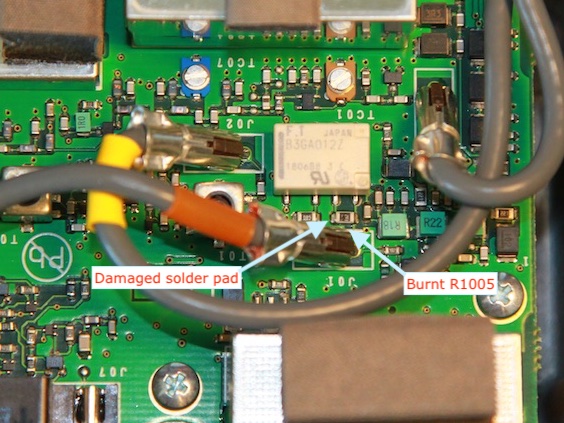
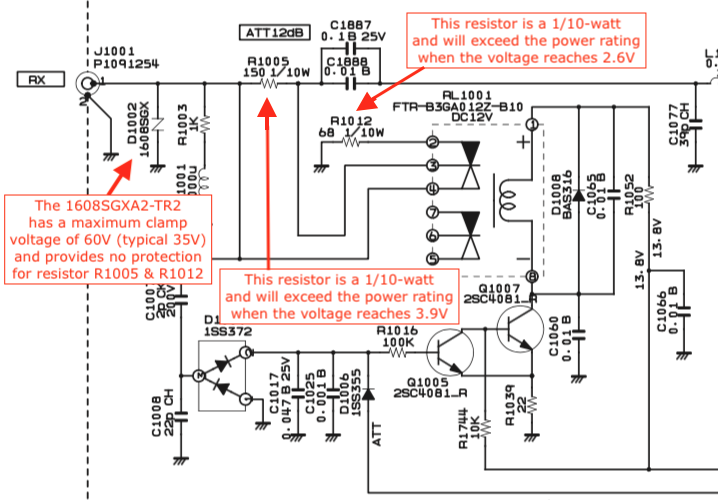
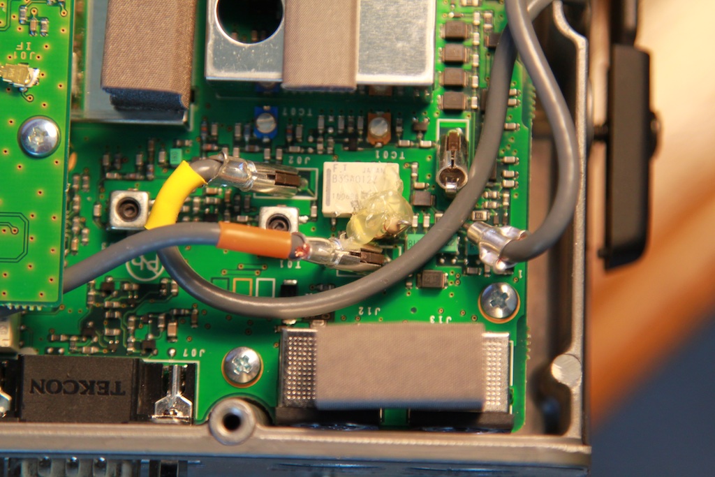
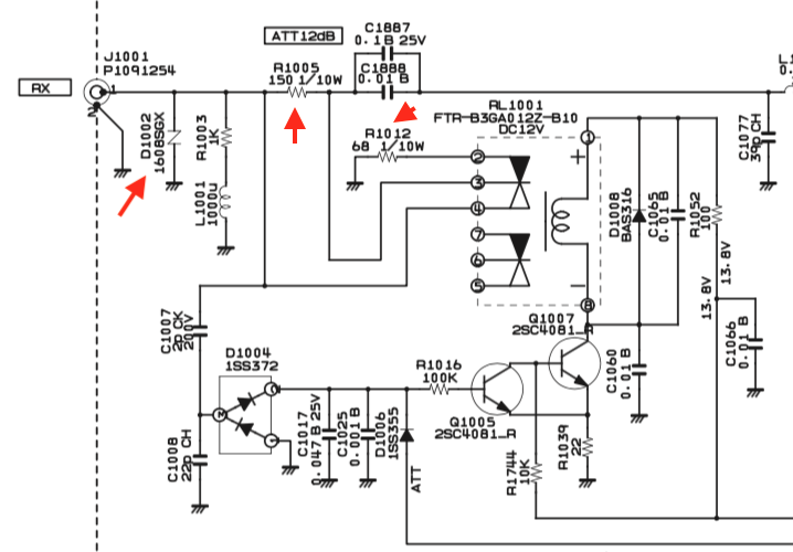
The following image depicts the relevant section of the FT-991A receiver front end schematic. It can be seen that the Attenuator circuit if formed with a 150Ω and 68Ω resistor voltage divider that is comprised of R1005 and R1012. When the Attenuator is disabled, the 150Ω R1005 is shorted by relay contacts and the 68Ω R1012 is removed from the circuit by relay contacts. The failure mode is due to the 150Ω R1005 opening up and breaking the signal path.


Yaesu_FT-991_Schematic.png

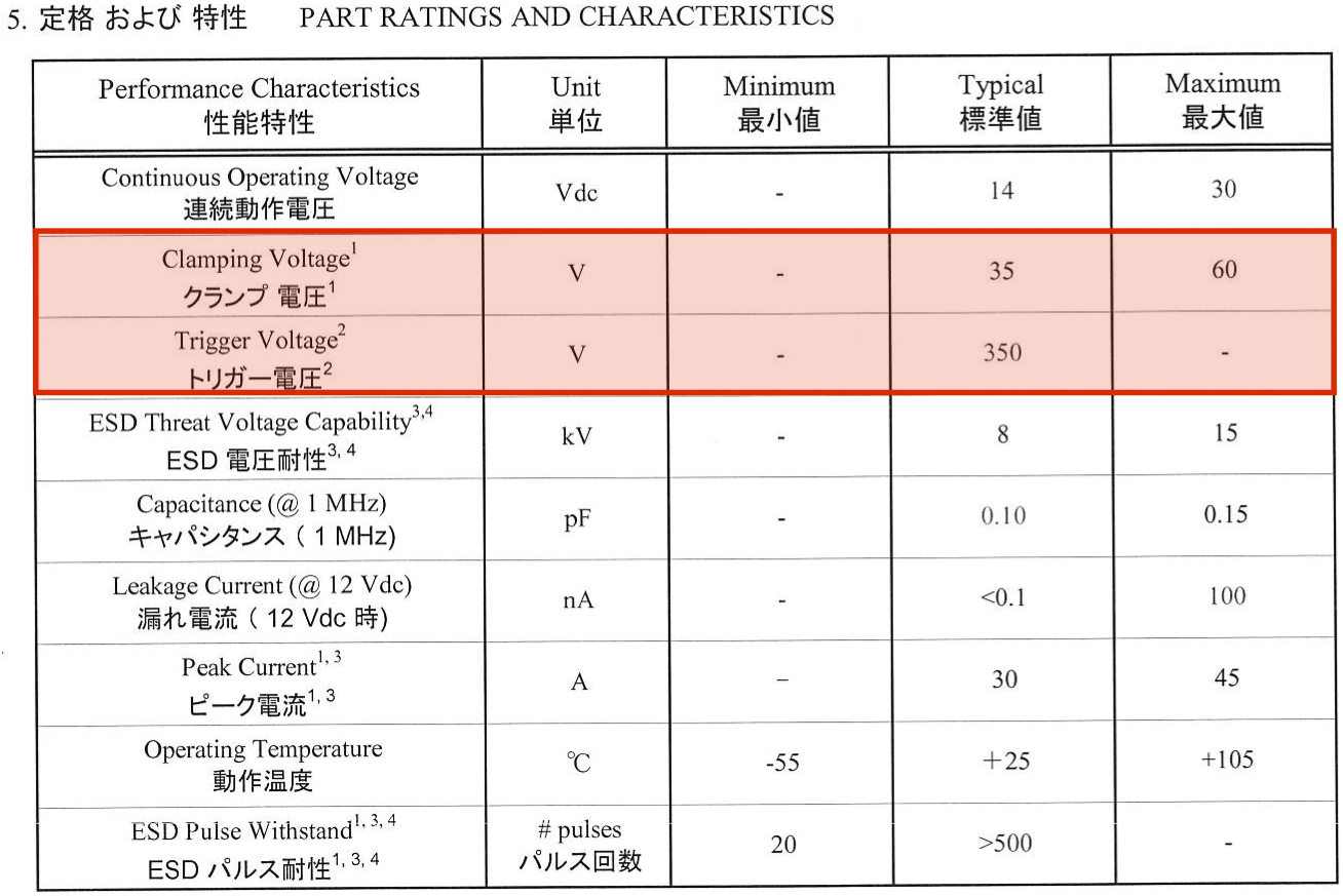
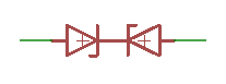
The surge protector at D1002 (Mfr. P/N 1608SGXA2-TR2) is expected to protect the resistor divider of R1005 and R1012 from experiencing voltages that exceed the 1/10-watt rating of both of these resistors, and it was initially suspected that the surge protector may have failed.

Upon opening the radio, it was confirmed that R1005 had burned and also heated the solder pad, breaking the circuit. If 3.9V is applied across R1005, power dissipation will reach 1/10W. With 3.9V across R1005, a current of 26mA. Applying 26mA of current ot the 68Ω R1012 results in a voltage drop of approximately 1.8V. The maximum voltage that can then be applied across the entire voltage divider is approximately 5.7 volts. A copy of the datasheet for the D1002 surge protector has a maximum clamping voltage of 60V (35V typical) and with a trigger voltage of 350V, which is far above the 5.7 volt level and provides no protection for the resistor components in the Attenuator circuit.


IMG_6626.jpg
Yaesu_FT-991_Schematic.png

It appears that the surge protector was improperly selected to protect the Attenuator circuit, and appears to be a design issue. Regardless, because of the lack of protection, and the high clamping voltage, failure of D1002 is no longer suspect. The reason that the 68Ω R1012 did not fail is that the total voltage across the Attenuator would need to reach 6.5 volts to result in exceeding the power rating of R1012 and the 150Ω R1005 would have failed at a lower total voltage across the Attenuator circuit.


Yaesu_FT-991_Schematic_annotated.png

Repair was done by replacing the surface mounted 1/10 watt R1005 with a resistor of a higher power rating. A 1/4-watt 150Ω resistor was soldered to the relay pads at RL1001.


Note that the author suffers from a physical disability, due to spinal cord injury, and no longer possesses the dexterity to work surface mount devices. Put on a pair of mittens and you'l have some idea of the difficulty experienced. If you have the equipment, and the physcial ability, certainly SMD techniques should be employed.


IMG_6631.jpg

A hot-glue gun was used to glue the resistor to the side of the relay to provide mechanical relief so that the solder pads for the relay do not become damaged from any mechanical mishandling.


IMG_6635.jpg

Although there was some concern that replacing R1005 with a higher wattage resistor might leave R1012 vulnerable to failure, results thus far has shown no further failure for the station configuration that previously experienced failure of R1005. Had additional failures occurred, the next step would have been to replace diode D1002 with a Zener diode array that is selected to limit the total voltage across the Attenuator circuit to 5-volts or less so that the Attenuator is properly protected from voltages that would exceed the power rating of the resistors in the Attenuator circuit. The following configuration may be favorable when compared to the DIAC installed at D1002:


diode_array.png

The root cause of the failure is due to the selection of a surge suprressor device that has a clamping voltage that exceeds the maximum voltage of the components in the Attenuator circuit if the power dissipation of the Attenuator circuit resistors is to be maintained within the limits of the resistor components. Voltages that exceed the maximum voltage that would result in damage to the resistors in the Attenuator are possible without the surge protector going into a mode of conduction.


NOTE 1:

If the receiver is presented with a strong RF field, the incoming RF will be half-wave rectified by D1004, resulting in a DC bias at the base of transistor Q1005 that places Q1005 into saturation. This is the same condition as the Attenuator enable signal and enables the Attenuator, placing the Attenuator into the very mode where the strong RF field can damage R1005. This circuit behavior seems to be a reasonable design goal in that the receiver Attenuator is placed into the circuit in a strong RF environment to protect the receiver front-end. However, since the Attenuator is not properly designed to handle strong RF levels that produce several volts at the receiver input, and under the operating conditions where a sufficiently high voltage is generated at the receiver input, this circuit behavior is likely to result in receiver failure.

With the Attenuator being automatically placed into an active mode in the presence of a strong RF field, there is no operator work-around to avoid this issue. It is recommended that the FT-991A not be operated in a strong RF environment (as may occur in a multi-op station configuration). Using this radio in support of a club Field Day event with a mult-operator configuration is probably not a good idea.


NOTE 2:

An unconfirmed report (not provided by an owner of an FTDX-3000 and no source citation) of a similar issue on the FTDX-3000 was received. There are similarites and differences between the FTDX-3000 and the FT-991A. The FT-991A has a single stage attenuator circuit that provides -12dB of attenuation. The FTDX-3000 has two-stages of attenuation, with the first stage proiding -6dB of attenuation and the second stage providing -12dB of attenuation.

The FTDX-3000 requires evaluation of the first stage -6dB attenuator, and a separate evaluation of the second stage -12dB attenuator when the first stage attenuator is disabled (i.e. 0dB).

Both use the same surge suppressor device, and a similar resistor divider and relay circuit is used to implement the attenuator. However, the resistors used in the attenuator on the FTDX-3000 differ both in value and power rating. The following table provides a comparison:


RADIO CIRCUIT COMPONENT VALUE POWER
RATING
VOLTAGE
AT
POWER
LIMIT
CURRENT
AT
POWER
LIMIT
FT-991A -12dB ATT R1005 150Ω 1/10W 3.9 26mA
R1012 68Ω 1/10W 2.6 38mA
FTDX-3000 -6dB ATT R1007 47Ω 1/4W 3.4 72mA
R1005 100Ω 1/4W 5.0 50mA
-12dB ATT R1024 150Ω 1/4W 6.1 41mA
R1023 68Ω 1/4W 4.1 68mA

Viewing the above table shows that the -12dB attenuator found in the FTDX-3000 is identical to the -12dB attenuator found in the FT-991A except that the FTDX-3000 uses 1/4W resistors where the FT-991A uses 1/10W resistors.

For either attenuator circuit, it is the resistor that reaches its power rating at a lower current that will determine the voltage at the input of the attenuator circuit that may result in failure.

For the -6dB attenuator, the R1005 / 100Ω will reach max power at 50mA of current. Applying 50mA of current to the series R1005 / 100Ω and R1007 / 47Ω resistor shows reaching the failure point at 7.3V at the input of the attenuator circuit.

For the -12dB attenuator, the R1024 / 150Ω will reach max power at 41mA of current. Applying 41mA of current to the series R1024 / 150Ω and R1023 / 68Ω resistor shows reaching the failure point at 8.9V at the input of the attenuator circuit.

Both FTDX-3000 attenuators provide a substantially higher margin than the attenuator found in the FT-991A. It is not known whether the margin is or is not adequate to support operation with a strong RF Field. What can be said is that voltages that result in exceeding the power rating of the resistors used in the attenuator circuits are possible and that are well below the threshold of protection offerred by the 1608SGXA2 at D1001.


NOTE 3:

If the radio is not operatred in an environment with strong RF from another transmitter, it is extremely unlikely that the user will ever experience the issue described in this document.


NOTE 4:

Implementing the rework found in this article will void the warranty on the radio. This article was written to disclose the cause of the problem and one solution to restore proper operation of the radio.

Working with surface mounted components, the printed circuit board, and applying non surface mounted components on a printed circuit board layout that was not designed for them, requires proper equipment and the requisite soldering skills. If you do not possess the proper equipment or the proper skill level, please do not attempt to implement the rework described in this document.

If you decide to implement the rework described in this article, you assume all risk in doing so.