Hawaii
|
Alaska
|
Pacific
|
Mountain
|
Central
|
Eastern
|
Puerto Rico
|
UTC
|
Guam
|
|
|
|
Icom AH4 SGC Tuner Protocol Converter
|
|
|
|
Version 1.00
|
|
|
|
|
|
Copyright © 2020 Raymond B Montagne All rights reserved.
|
|
|
Table of Contents
A pdf copy of this article is available by clicking
HERE.
Overview
This project was developed to interface the SGC auto-tuner to a transciever that supports the
Icom AH4 auto-tuner protocol. The target transceiver, supporting the AH4 protocol, that was used
to develop this project is the Icom IC-F8101-33,
which is interfaced to an
SGC SG-230 auto-tuner that is connected to an
SGC SG-303 helically wound mobile whip antenna.
Features supported include:
-
Automated management of locking the SGC SG-230
tuner before and after completing an auto-tune cycle
-
Unsuccessful auto-tune cycles will result in the SGC SG-230
being automatically placed into bypass mode
-
The SGC SG-230 auto-tuner
can also be placed into bypass mode using the Icom AH4 auto-tuner protocol
-
Support any SGC auto-tuner that uses a 4-wire control interface
-
Support any transceiver that supports the Icom AH4 auto-tuner protocol
The translation between the Icom AH4 auto-tuner protocol and the SGC auto-tuner protocol is implemented
with an Arduino Pro Micro microcontroller and peripheral MOSFET circuitry to interface the Icom AH4 auto-tuner
interface on the transceiver to the SGC auto-tuner. The SGC auto-tuner LOCK/RESET/BYPASS signal is a tri-state
signal that can be driven high (locked), drive low (reset/bypass), or left in a high-impedance state
(unlocked), with the interface circuit providing protection against simultaneously driving the tri-state
signal low and high.
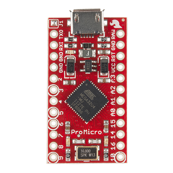
The programming of the Arduino is written in standard C language syntax.
Source code is provided.
Operation
Operation of the Icom AH4 to SGC auto-tuner protocol converter is controlled by the Icom transceiver
user interaface. A TUNE button is provided on the transceiver to manually invoke an auto
tuning sequence. Icom transceivers, such as the IC-F8101, may include an internal
setting that allows auto-tuning to be invoked when the push-to-talk (PTT) is activated.
The Icom IC-F8101-33 is a 125-watt HF Transceiver that supports Mil Std 188-141 Automatic Link Establishment (ALE),
holds an FCC LMR Part 90 type certification, is approved for operation on NTIA frequencies, and has an
optional Rapid M110A modem (suitable for Air Force, Army MARS, USCG Auxiliary and DHS CISA SHARES operation). The IC-F8101 series
supports the Icom AH4 Auto-Tuner protocol, and integrates management of the auto-tuner directly into
the ALE calling protocols. ALE requires an auto-tuner that can arrive rapidly at a tuned solution
without imposing significant delay to the ALE channel scan group dwell time, and with the SGC
auto-tuners meeting this requirement with its memory tuning feature, the IC-F8101 and SGC auto-tuner
appear to be well matched. The IC-F8101 can be used on Amateur Radio HF frequencies,
but its intended market primarily targets Local, State and Federal Government radio communications facilities.
Using the front panel on the Icom IC-F8101-33,
operation is as follows:

-
NORMAL TUNING: Press and hold the TUNE button on the front panel (highlighted in a yellow rectangle in
the image above) until the transmit side-tone starts, then immediately release the TUNE button
when the side-tone is heard. The transmitter will continue to transmit,
and emit the side-tone, until tuning completes or fails. Check the LED status to determine
if the auto-tune sequence was successful. A successful auto-tune sequence by observing that
both the TUNED and LOCKED LEDs are illuminated.
If the LOCKED LED is illuminated while the TUNED LED is not illuminated, the auto-tune
sequence was not successful and the SGC auto-tuner is in BYPASS mode.
In some installations, such as when using an Icom IC-F8101 with a remote control head, the LED status of the
Icom AH4 SGC Protocol Converter may not be visible from the operating position. In this case, a short tuning
cycle, as indicated by the duration of the transceiver side-tone, is indicative of a successful auto-tuning
sequence. A long tuning cycle may be ambiguous, as indicated by the duration of the transceiver side-tone,
in indicating a successful auto-tuning sequence when the LED status is not viewable from the operating
position. In this case, a second auto-tuning seuqence can be initiated, and if the second auto-tuning
sequence is short (where the auto-tuning parameters were pulled from the auto-tuner memory), the
auto-tuning sequence was successful. If the second auto-tuning sequence is also long, the auto-tuning
sequence was not successful and transmission should be avoided until the auto-tuning failure can be
resolved.
-
BYPASS TUNING: Press the TUNE button and then quickly release the TUNE button on the front panel. The TUNE button
should be released before the transmitter emits a side-tone. No transmission will occur. Bypass
mode can be verified by checking that the LOCKED LED is illuminated while the TUNED LED is not illuminated.
The recommended operation is to sequence through all memory resident channels and perform an auto-tune
operation on each channel after installation of the tuner and the protocol converter. This will
allow the SGC auto-tuner to memorize the tuning parameters for each channel, resulting in the ability
to rapdily tune on channels that have been stored in the auto-tuner memory after selecting a new channel.
This task is absolutely necessary for Automatic Link Establishment (ALE) operations.
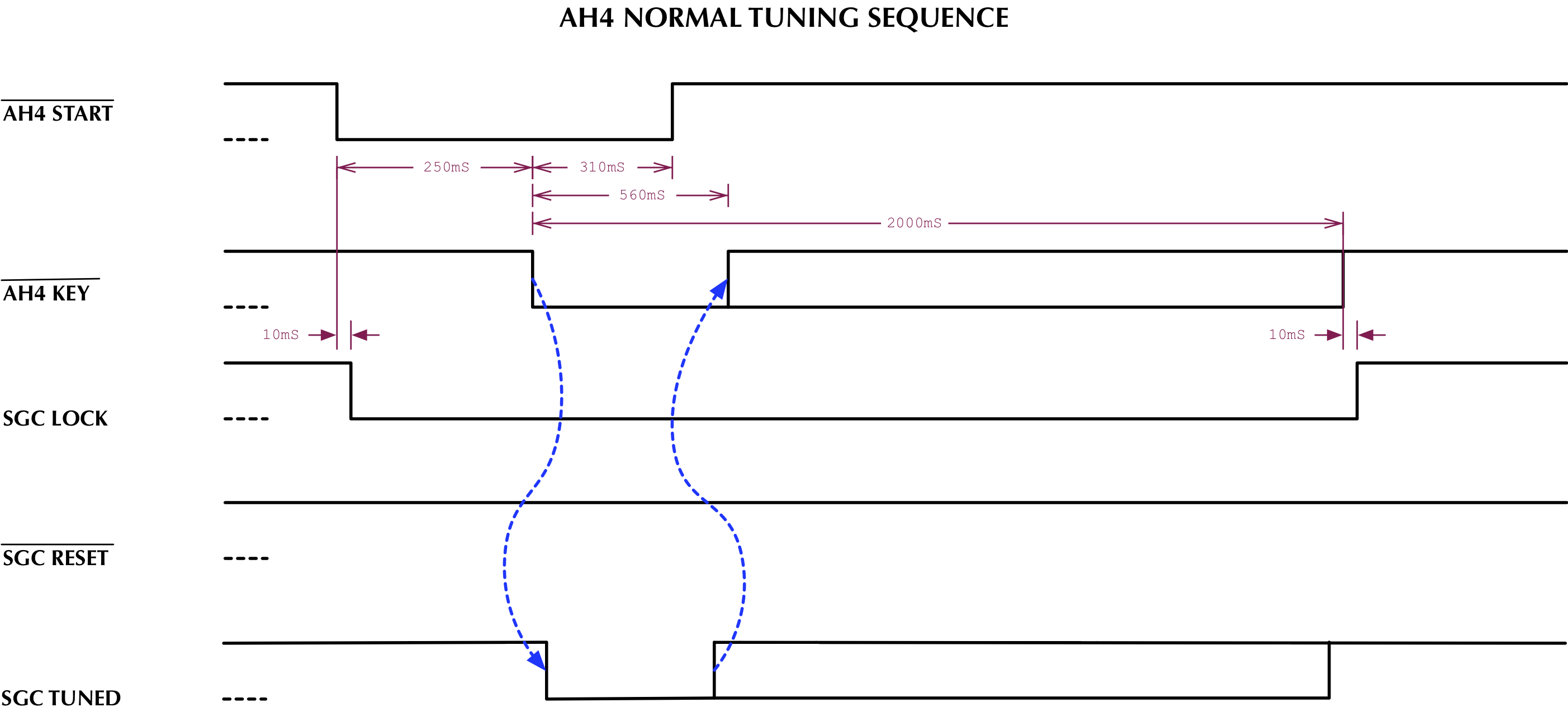
Timing Diagrams
The following timing diagram shows a successful Icom AH4 auto-tuning cycle, and the management of
the SGC auto-tuner lock control. The SGC auto-tuner is placed into an unlocked state at the beginning
of the auto-tune cycle, allowing the auto-tune cycle to execute. Once the SGC auto-tuner indicates
that tuning was successful, the SGC auto-tuner is placed into a locked state to prevent an auto-tuning
cycle to occur during normal transmitter operation.
The following timing diagram shows an unsuccessful Icom AH4 auto-tuning cycle, and the management of
the SGC auto-tuner lock and reset controls. When the SGC auto-tuner fails to indicate a successful
auto-tune sequence, the SGC auto-tuner is placed into bypass mode and then locked.
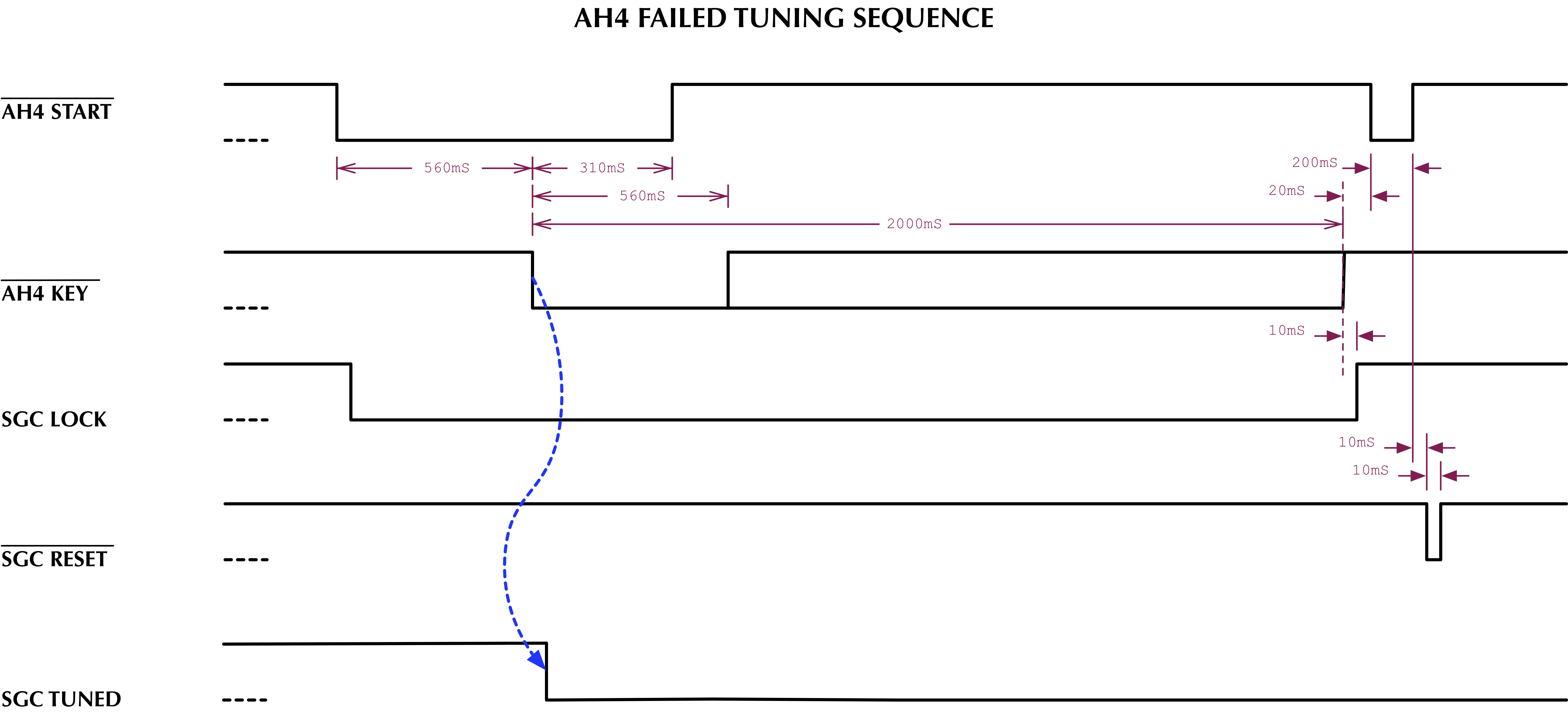
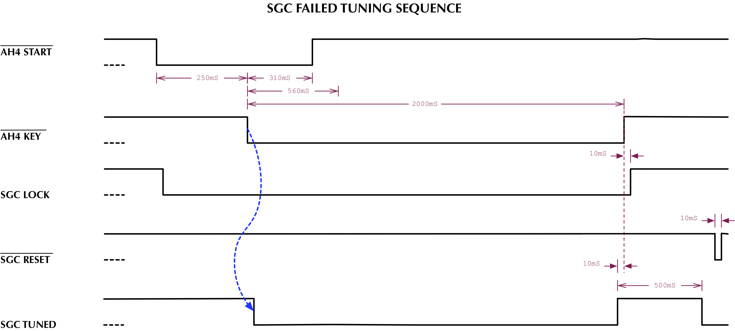
The SGC auto-tuner can also indicate a failed auto-tune sequence. When failure occurs, the SGC auto-tuner
will first indicate a TUNED solution, but will then negate the TUNED signal 500 milliseconds after
first indicating a TUNED solution. The protocol converter will respond to this sequence by placing the
auto-tuner into the bypass mode.
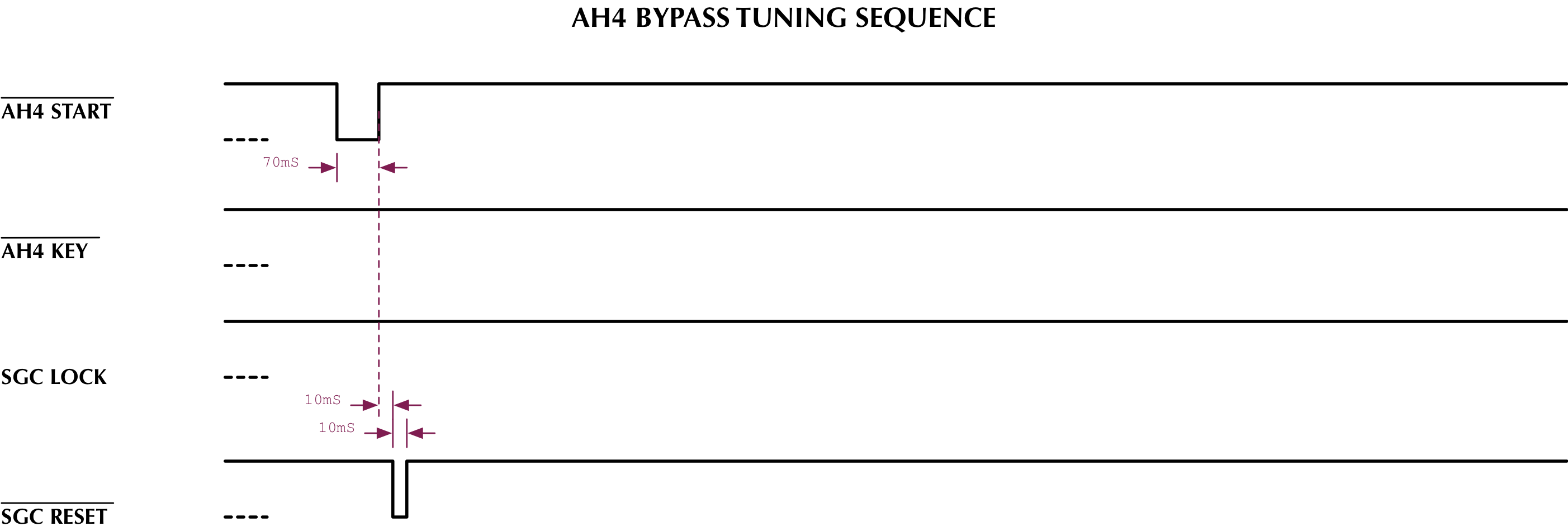
The following timing diagram shows the Icom AH4 protocol issuing a command to place the tuner into
bypass mode. In response to this command, the SGC auto-tuner is placed into bypass mode and then
locked.
Schematic
All signals between the transciever's Icom AH4 auto-tuner interface and the protocol convertern,
and between the protocol converter and the SGC auto-tuner are buffered with MOSFET devices. Q6 serves
to inhibt Q7 when the SGC inteface LOCK/RESET/BYPASS signal is being driven low to prevent Q1 from simultaneously
driving the the LOCK/RESET/BYPASS signal high. All MOSFET devices operate in saturation or cut-off
mode. Similar to SGC's lock device, this protocol converter has the SGC interface operating
at 8.0 volts.
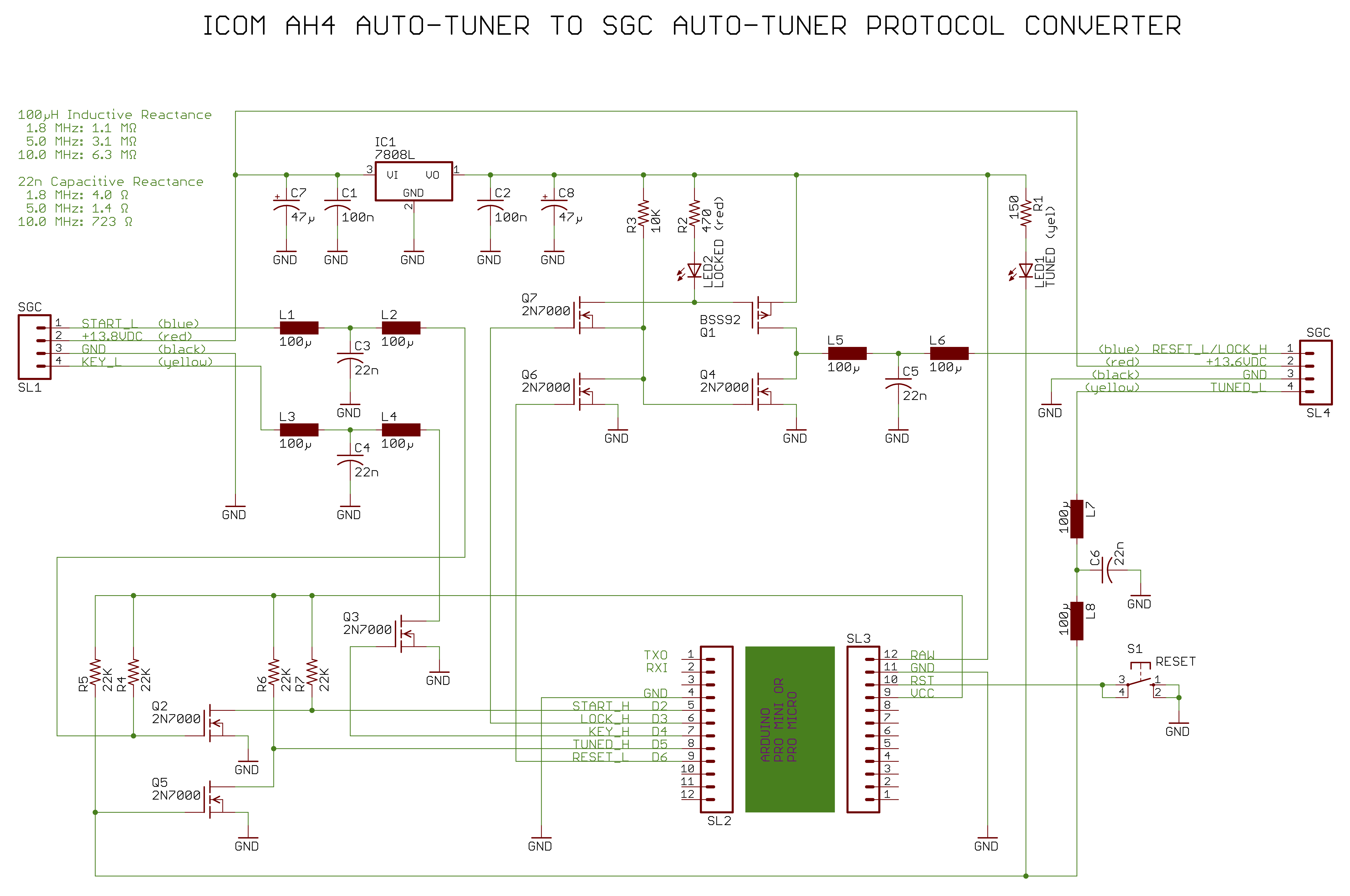
Note that a VP0106N3-G P-CHANNEL MOSFET, available from DigiKey, was used at Q1. No library
component for this MOSFET was available in the Eagle CAD software that was used to produce the
schematic.
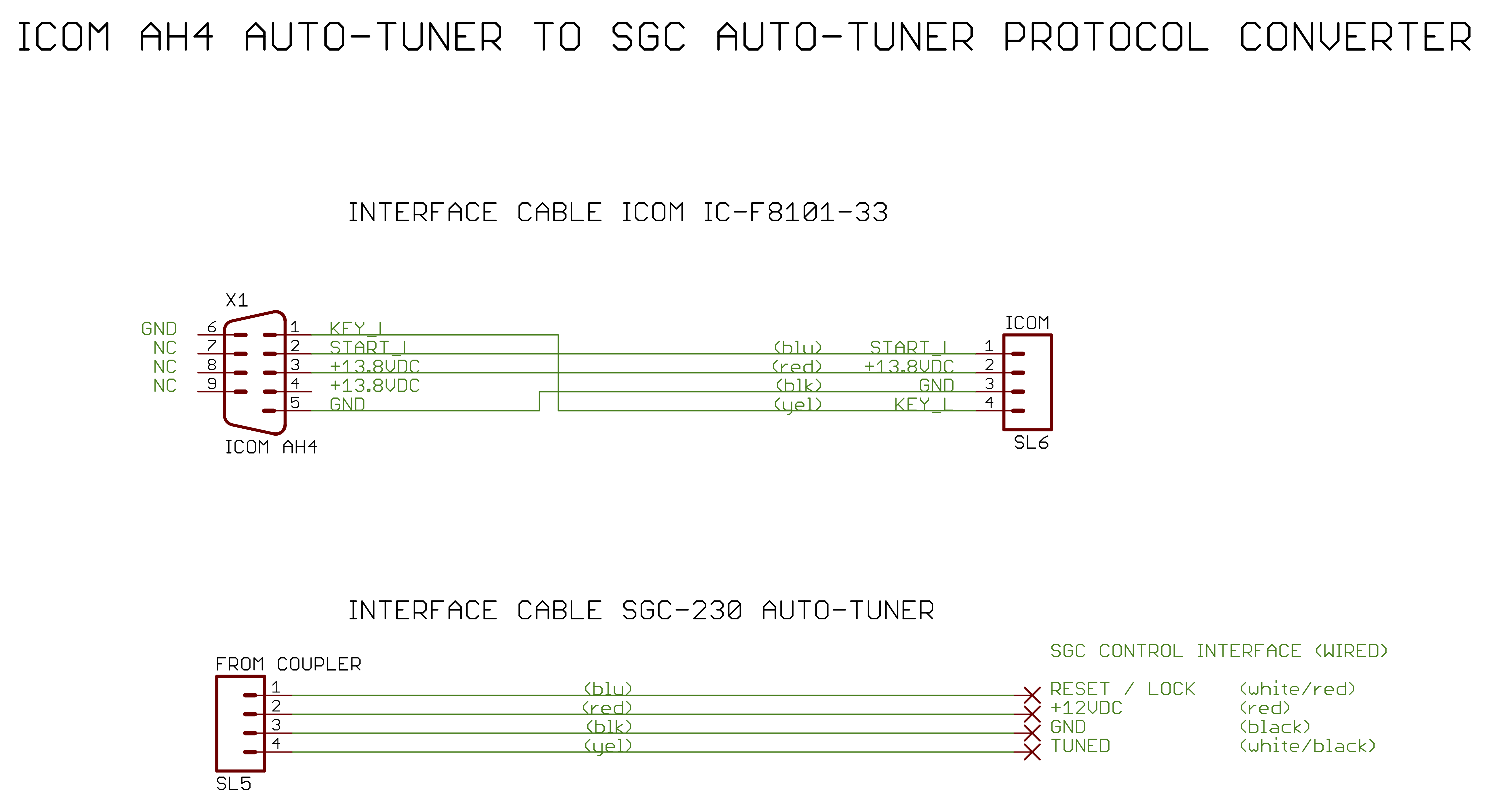
Cable Assembly
The following schematic depicts the cable assemblies that interface the protocol converter board to
the Icom transceiver and the SGC auto-tuner:
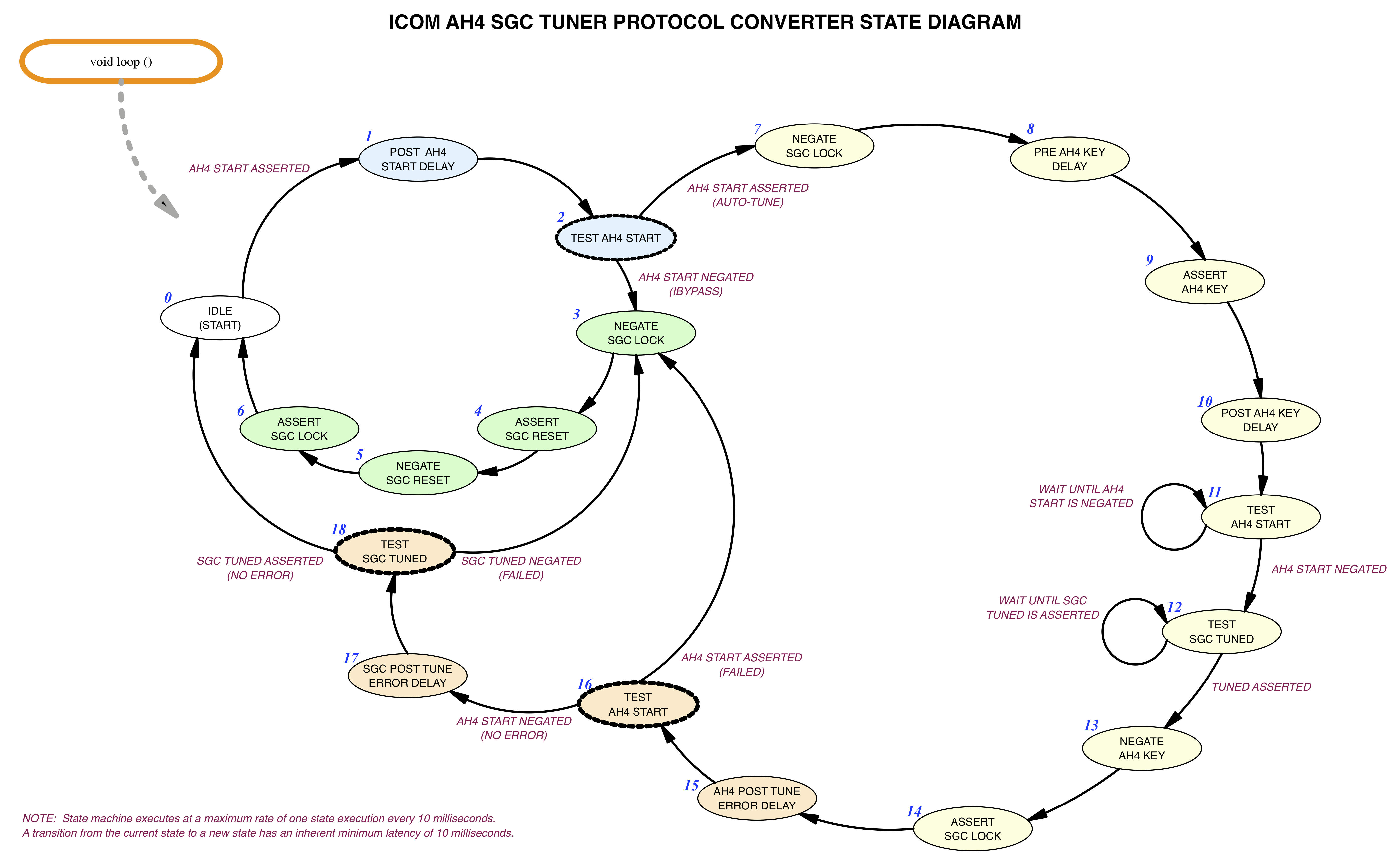
Software State Machine
The following depicts that state machine diagram for the acocmpanying C language source code.
State machine event
transition notes are indicated in maroon text. Light blue cells
are associated with Icom AH4 tuner command detection. Light yellow cells are associated with the
auto-tuning process. Peach colored cells are associated with auto-tune error detection. Light
green cells are associated with placing the auto-tuner into bypass mode. Cells with a bold dashed
border indicate a decision point.
C-Language Source Code
The source code provides the standard Arduino setup function, which is
used to initialize the Icom AH4 and SGC auto-tuner interfaces. The standard Arduino
loop function implements the state machine, which provides the
protocol translation between the Icom AH4 and SGC auto-tuner protocols. The loop
function is coded to execute the state maching at a minimum delay interval of 10 milleseconds per state,
making it simple to implement timing delays with a 10 millisecond resolution.
Initialization occurs during the setup ()
function. Initialization tasks include:
-
Table driven initialization of General Purspose I/O (GPIO) pins, including:
-
Configuring the General Purpose I/O (GPIO) data direction registers.
-
Initialization of Output GPIO state.
-
Initialization of global variables, including:
-
Initialize data structures for the LED state machine
-
Initialize variables for the auto-tuner state machine
After initialization, execution continues in the loop () function,
where the state machine monitors the AH4 START signal in order to detect a
request from the transceiver to initiate tuning. Once a tuning request
occurs, the AH4 START signal is re-sampled 100 milliseconds after detecting the auto-tune
request to determine if the auto-tune request is commanding a request to enter tuner bypass
mode or to initiate an auto-tune sequence. See light blue cells in the state machine diagram.
If the request from the transciever is to enter bypass mode, the SGC LOCK signal is negated, the
SGC RESET signal is asserted and negated (placing the tuner into bypass mode), and then the SGC
LOCK signal is asserted to prevent the SGC tuner from entering an auto-tune sequence.
See light green cells in the state machine diagram.
If the request from the transceiver is to enter an auto-tune sequence, handshaking with the
transceiver, using the AH4 KEY line will be initiated. The SGC TUNED status will be monitored
to determine when the AH4 KEY line should be negated. After the auto-tune sequence has
completed, the SGC auto-tuner is placed into a LOCKED state. Timing requirements of the
Icom AH4 auto-tuner protocol are maintained during the auto-tuning sequence.
See light yellow cells in the state machine diagram.
After an auto-tune sequence has completed, the AH4 START signal is checked to see if the
transceiver indicates an error. If no transceiver error occurs, the SGC TUNED status is
checked to see if an error has been detected by the SGC auto-tuner.
See peach colored cells in the state machine diagram.
const unsigned int kPIN__AH4_START_H = 2;
const unsigned int kPIN__SGC_LOCK_H = 3;
const unsigned int kPIN__AH4_KEY_H = 4;
const unsigned int kPIN__SGC_TUNED_H = 5;
const unsigned int kPIN__SGC_RESET_L = 6;
const unsigned int kPIN__START_DETECT_LED_L = 17;
const unsigned int kPIN__KEYED_LED_L = 30;
const unsigned int kTUNE_START_ASSERTED = HIGH;
const unsigned int kTUNE_START_NEGATED = LOW;
const unsigned int kLOCK_ASSERTED = HIGH;
const unsigned int kLOCK_NEGATED = LOW;
const unsigned int kKEY_ASSERTED = HIGH;
const unsigned int kKEY_NEGATED = LOW;
const unsigned int kTUNED_ASSERTED = HIGH;
const unsigned int kTUNED_NEGATED = LOW;
const unsigned int kRESET_ASSERTED = LOW;
const unsigned int kRESET_NEGATED = HIGH;
const unsigned int kKEY_LED_ASSERTED = LOW;
const unsigned int kKEY_LED_NEGATED = HIGH;
const unsigned int kSTART_DETECT_LED_ASSERTED = LOW;
const unsigned int kSTART_DETECT_LED_NEGATED = HIGH;
typedef struct {
uint8_t pin_address;
uint8_t pin_data_direction;
uint8_t pin_initial_state;
} PIN_INITIALIZATION_STRUCT;
const PIN_INITIALIZATION_STRUCT kPIN_INITIALIZATION_TABLE[] = {
{ kPIN__AH4_START_H, INPUT_PULLUP, HIGH },
{ kPIN__SGC_LOCK_H, OUTPUT, kLOCK_NEGATED },
{ kPIN__AH4_KEY_H, OUTPUT, kKEY_NEGATED },
{ kPIN__SGC_TUNED_H, INPUT_PULLUP, HIGH },
{ kPIN__SGC_RESET_L, OUTPUT, kRESET_NEGATED },
{ kPIN__KEYED_LED_L, OUTPUT, kKEY_LED_ASSERTED },
{ kPIN__START_DETECT_LED_L, OUTPUT, kSTART_DETECT_LED_NEGATED } };
const int kPIN_LOOP_COUNT = sizeof ( kPIN_INITIALIZATION_TABLE ) / sizeof ( PIN_INITIALIZATION_STRUCT );
const unsigned int kSTATE_MACHINE_INTERVAL = 10;
const unsigned int kAH4_START_100mSEC_DELAY = ( 100 / kSTATE_MACHINE_INTERVAL );
const unsigned int kAH4_START_TO_KEY_DELAY = ( 150 / kSTATE_MACHINE_INTERVAL );
const unsigned int kAH4_START_320mSEC_DELAY = ( 320 / kSTATE_MACHINE_INTERVAL );
const unsigned int kAH4_START_10mSEC_DELAY = ( 10 / kSTATE_MACHINE_INTERVAL );
const unsigned int kAH4_START_500mSEC_DELAY = ( 500 / kSTATE_MACHINE_INTERVAL );
const unsigned int kLED_SLOW_BLINK_TIMER_SEED = ( 500 / kSTATE_MACHINE_INTERVAL );
const unsigned int kLED_FAST_BLINK_TIMER_SEED = ( 100 / kSTATE_MACHINE_INTERVAL );
enum {
kTUNING_STATES__IDLE = 0,
kTUNING_STATES__AH4_POST_START_DELAY,
kTUNING_STATES__TEST_AH4_START_BYPASS,
kTUNING_STATES__BYPASS_NEGATE_SGC_LOCK,
kTUNING_STATES__BYPASS_ASSERT_SGC_RESET,
kTUNING_STATES__BYPASS_NEGATE_SGC_RESET,
kTUNING_STATES__BYPASS_ASSERT_SGC_LOCK,
kTUNING_STATES__TUNE_UNLOCK,
kTUNING_STATES__TUNE_PRE_AH4_KEY_DELAY,
kTUNING_STATES__TUNE_ASSERT_AH4_KEY,
kTUNING_STATES__TUNE_POST_AH4_KEY_DELAY,
kTUNING_STATES__TUNE_WAIT_AH4_START_NEGATE,
kTUNING_STATES__TUNE_WAIT_SGC_TUNED,
kTUNING_STATES__TUNE_NEGATE_AH4_KEY,
kTUNING_STATES__TUNE_ASSERT_SGC_LOCK,
kTUNING_STATES__TUNE_AH4_POST_TUNE_ERROR_DELAY,
kTUNING_STATES__TUNE_TEST_AH4_TUNE_FAIL,
kTUNING_STATES__TUNE_SGC_POST_TUNE_ERROR_DELAY,
kTUNING_STATES__TUNE_TEST_SGC_TUNE_FAIL,
kTUNING_STATES__NUM_STATES
} TUNING_STATES;
enum {
kLED_OFF = 0,
kLED_ON_SOLID,
kLED_ON_SLOW_BLINK,
kLED_ON_FAST_BLINK,
kNUM_LED_COMMANDS
} LED_COMMANDS;
enum {
kGREEN_KEY_LED_STATE_MACHINE = 0,
kYELLOW_START_LED_STATE_MACHINE,
kNUM_LED_STATE_MACHINES
} LED_STATE_MACHINE_INDEX;
typedef struct {
unsigned int led_pin;
unsigned int led_command;
unsigned int led_timer;
unsigned int led_assert;
boolean led_state;
} LED_STATE_MACHINE;
typedef struct {
unsigned int tuner_state_machine;
unsigned long int masterTime;
unsigned int stateExecutionTimer;
unsigned int delayTimer;
LED_STATE_MACHINE led_machines[kNUM_LED_STATE_MACHINES];
} ALL_GLOBALS;
ALL_GLOBALS globals;
void setAh4TunerKeyState ( int ah4KeyState )
{
digitalWrite ( kPIN__AH4_KEY_H, ah4KeyState );
}
void setSgcTunerLockState ( int sgcLockState )
{
digitalWrite ( kPIN__SGC_LOCK_H, sgcLockState );
}
void setSgcTunerResetState ( int sgcResetState )
{
digitalWrite ( kPIN__SGC_RESET_L, sgcResetState );
}
boolean ah4TuneStartIsAsserted ( void )
{
return kTUNE_START_ASSERTED == digitalRead ( kPIN__AH4_START_H );
}
boolean sgcTunedIsAsserted ( void )
{
return kTUNED_ASSERTED == digitalRead ( kPIN__SGC_TUNED_H );
}
void set_led_command ( unsigned int led_index, unsigned int led_command )
{
if ( kNUM_LED_STATE_MACHINES > led_index && kNUM_LED_COMMANDS > led_command )
{
globals.led_machines[led_index].led_command = led_command;
}
}
void led_state_machine ()
{
unsigned int timer_seed = 0;
for ( int index = 0; index < kNUM_LED_STATE_MACHINES; index++ )
{
switch ( globals.led_machines[index].led_command )
{
case kLED_OFF:
{
digitalWrite ( globals.led_machines[index].led_pin,
HIGH == globals.led_machines[index].led_assert ? LOW : HIGH );
globals.led_machines[index].led_state = false;
globals.led_machines[index].led_timer = 0;
}
break;
case kLED_ON_SOLID:
{
digitalWrite ( globals.led_machines[index].led_pin,
HIGH == globals.led_machines[index].led_assert ? HIGH : LOW );
globals.led_machines[index].led_state = true;
globals.led_machines[index].led_timer = 0;
}
break;
case kLED_ON_SLOW_BLINK:
case kLED_ON_FAST_BLINK:
{
switch ( globals.led_machines[index].led_command )
{
case kLED_ON_SLOW_BLINK: timer_seed = kLED_SLOW_BLINK_TIMER_SEED; break;
case kLED_ON_FAST_BLINK: timer_seed = kLED_FAST_BLINK_TIMER_SEED; break;
}
if ( 0 == globals.led_machines[index].led_timer )
{
globals.led_machines[index].led_timer = timer_seed;
}
globals.led_machines[index].led_timer--;
if ( 0 == globals.led_machines[index].led_timer )
{
if ( globals.led_machines[index].led_state )
{
digitalWrite ( globals.led_machines[index].led_pin,
HIGH == globals.led_machines[index].led_assert ? LOW : HIGH );
globals.led_machines[index].led_state = false;
}
else
{
digitalWrite ( globals.led_machines[index].led_pin,
HIGH == globals.led_machines[index].led_assert ? HIGH : LOW );
globals.led_machines[index].led_state = true;
}
globals.led_machines[index].led_timer = timer_seed;
}
}
break;
}
}
}
void auto_tune_state_machine ( void )
{
switch ( globals.tuner_state_machine )
{
case kTUNING_STATES__IDLE:
{
if ( ah4TuneStartIsAsserted () )
{
globals.delayTimer = kAH4_START_100mSEC_DELAY;
globals.tuner_state_machine = kTUNING_STATES__AH4_POST_START_DELAY;
}
}
break;
case kTUNING_STATES__AH4_POST_START_DELAY:
{
if ( 0 != globals.delayTimer )
{
globals.delayTimer--;
if ( 0 == globals.delayTimer )
{
globals.tuner_state_machine = kTUNING_STATES__TEST_AH4_START_BYPASS;
}
}
else
{
set_led_command ( kYELLOW_START_LED_STATE_MACHINE, kLED_ON_SLOW_BLINK );
set_led_command ( kGREEN_KEY_LED_STATE_MACHINE, kLED_OFF );
globals.tuner_state_machine = kTUNING_STATES__TEST_AH4_START_BYPASS;
}
}
break;
case kTUNING_STATES__TEST_AH4_START_BYPASS:
{
if ( ah4TuneStartIsAsserted () )
{
globals.tuner_state_machine = kTUNING_STATES__TUNE_UNLOCK;
}
else
{
set_led_command ( kYELLOW_START_LED_STATE_MACHINE, kLED_OFF );
set_led_command ( kGREEN_KEY_LED_STATE_MACHINE, kLED_ON_SLOW_BLINK );
globals.tuner_state_machine = kTUNING_STATES__BYPASS_NEGATE_SGC_LOCK;
}
}
break;
case kTUNING_STATES__BYPASS_NEGATE_SGC_LOCK:
{
setSgcTunerLockState ( kLOCK_NEGATED );
globals.tuner_state_machine = kTUNING_STATES__BYPASS_ASSERT_SGC_RESET;
}
break;
case kTUNING_STATES__BYPASS_ASSERT_SGC_RESET:
{
setSgcTunerResetState ( kRESET_ASSERTED );
globals.tuner_state_machine = kTUNING_STATES__BYPASS_NEGATE_SGC_RESET;
}
break;
case kTUNING_STATES__BYPASS_NEGATE_SGC_RESET:
{
setSgcTunerResetState ( kRESET_NEGATED );
globals.tuner_state_machine = kTUNING_STATES__BYPASS_ASSERT_SGC_LOCK;
}
break;
case kTUNING_STATES__BYPASS_ASSERT_SGC_LOCK:
{
setSgcTunerLockState ( kLOCK_ASSERTED );
globals.tuner_state_machine = kTUNING_STATES__IDLE;
}
break;
case kTUNING_STATES__TUNE_UNLOCK:
{
setSgcTunerLockState ( kLOCK_NEGATED );
globals.delayTimer = kAH4_START_TO_KEY_DELAY;
globals.tuner_state_machine = kTUNING_STATES__TUNE_PRE_AH4_KEY_DELAY;
}
break;
case kTUNING_STATES__TUNE_PRE_AH4_KEY_DELAY:
{
if ( 0 != globals.delayTimer )
{
globals.delayTimer--;
if ( 0 == globals.delayTimer )
{
globals.tuner_state_machine = kTUNING_STATES__TUNE_ASSERT_AH4_KEY;
}
}
else
{
globals.tuner_state_machine = kTUNING_STATES__IDLE;
}
}
break;
case kTUNING_STATES__TUNE_ASSERT_AH4_KEY:
{
set_led_command ( kGREEN_KEY_LED_STATE_MACHINE, kLED_ON_SOLID );
setAh4TunerKeyState ( kKEY_ASSERTED );
globals.delayTimer = kAH4_START_320mSEC_DELAY;
globals.tuner_state_machine = kTUNING_STATES__TUNE_POST_AH4_KEY_DELAY;
}
break;
case kTUNING_STATES__TUNE_POST_AH4_KEY_DELAY:
{
if ( 0 != globals.delayTimer )
{
globals.delayTimer--;
if ( 0 == globals.delayTimer )
{
globals.tuner_state_machine = kTUNING_STATES__TUNE_WAIT_AH4_START_NEGATE;
}
}
else
{
globals.tuner_state_machine = kTUNING_STATES__IDLE;
}
}
break;
case kTUNING_STATES__TUNE_WAIT_AH4_START_NEGATE:
{
if ( !ah4TuneStartIsAsserted () )
{
globals.tuner_state_machine = kTUNING_STATES__TUNE_WAIT_SGC_TUNED;
}
}
break;
case kTUNING_STATES__TUNE_WAIT_SGC_TUNED:
{
if ( sgcTunedIsAsserted () )
{
globals.tuner_state_machine = kTUNING_STATES__TUNE_NEGATE_AH4_KEY;
}
}
break;
case kTUNING_STATES__TUNE_NEGATE_AH4_KEY:
{
set_led_command ( kGREEN_KEY_LED_STATE_MACHINE, kLED_OFF );
setAh4TunerKeyState ( kKEY_NEGATED );
globals.tuner_state_machine = kTUNING_STATES__TUNE_ASSERT_SGC_LOCK;
}
break;
case kTUNING_STATES__TUNE_ASSERT_SGC_LOCK:
{
setSgcTunerLockState ( kLOCK_ASSERTED );
globals.delayTimer = kAH4_START_10mSEC_DELAY;
globals.tuner_state_machine = kTUNING_STATES__TUNE_AH4_POST_TUNE_ERROR_DELAY;
}
break;
case kTUNING_STATES__TUNE_AH4_POST_TUNE_ERROR_DELAY:
{
if ( 0 != globals.delayTimer )
{
globals.delayTimer--;
if ( 0 == globals.delayTimer )
{
globals.tuner_state_machine = kTUNING_STATES__TUNE_TEST_AH4_TUNE_FAIL;
}
}
else
{
globals.tuner_state_machine = kTUNING_STATES__IDLE;
}
}
break;
case kTUNING_STATES__TUNE_TEST_AH4_TUNE_FAIL:
{
if ( ah4TuneStartIsAsserted () )
{
set_led_command ( kYELLOW_START_LED_STATE_MACHINE, kLED_ON_FAST_BLINK );
set_led_command ( kGREEN_KEY_LED_STATE_MACHINE, kLED_OFF );
globals.tuner_state_machine = kTUNING_STATES__BYPASS_NEGATE_SGC_LOCK;
}
else
{
globals.delayTimer = kAH4_START_500mSEC_DELAY;
globals.tuner_state_machine = kTUNING_STATES__TUNE_SGC_POST_TUNE_ERROR_DELAY;
}
}
break;
case kTUNING_STATES__TUNE_SGC_POST_TUNE_ERROR_DELAY:
{
if ( 0 != globals.delayTimer )
{
globals.delayTimer--;
if ( 0 == globals.delayTimer )
{
globals.tuner_state_machine = kTUNING_STATES__TUNE_TEST_SGC_TUNE_FAIL;
}
}
else
{
globals.tuner_state_machine = kTUNING_STATES__TUNE_TEST_SGC_TUNE_FAIL;
}
}
break;
case kTUNING_STATES__TUNE_TEST_SGC_TUNE_FAIL:
{
if ( sgcTunedIsAsserted () )
{
set_led_command ( kYELLOW_START_LED_STATE_MACHINE, kLED_ON_SLOW_BLINK );
set_led_command ( kGREEN_KEY_LED_STATE_MACHINE, kLED_OFF );
globals.tuner_state_machine = kTUNING_STATES__IDLE;
}
else
{
set_led_command ( kYELLOW_START_LED_STATE_MACHINE, kLED_OFF );
set_led_command ( kGREEN_KEY_LED_STATE_MACHINE, kLED_ON_FAST_BLINK );
globals.tuner_state_machine = kTUNING_STATES__BYPASS_NEGATE_SGC_LOCK;
}
}
break;
}
}
void setup ()
{
for ( int index = 0; index < kPIN_LOOP_COUNT; index++ )
{
pinMode ( kPIN_INITIALIZATION_TABLE[index].pin_address,
kPIN_INITIALIZATION_TABLE[index].pin_data_direction );
if ( OUTPUT == kPIN_INITIALIZATION_TABLE[index].pin_data_direction )
{
digitalWrite ( kPIN_INITIALIZATION_TABLE[index].pin_address,
kPIN_INITIALIZATION_TABLE[index].pin_initial_state );
}
}
for ( int index = 0; index < kNUM_LED_STATE_MACHINES; index++ )
{
switch ( index )
{
case kGREEN_KEY_LED_STATE_MACHINE:
{
globals.led_machines[index].led_pin = kPIN__KEYED_LED_L;
globals.led_machines[index].led_assert = kKEY_LED_ASSERTED;
}
break;
case kYELLOW_START_LED_STATE_MACHINE:
{
globals.led_machines[index].led_pin = kPIN__START_DETECT_LED_L;
globals.led_machines[index].led_assert = kSTART_DETECT_LED_ASSERTED;
}
break;
}
globals.led_machines[index].led_state = false;
globals.led_machines[index].led_timer = 0;
globals.led_machines[index].led_state = false;
}
globals.tuner_state_machine = kTUNING_STATES__IDLE;
globals.stateExecutionTimer = kSTATE_MACHINE_INTERVAL;
globals.delayTimer = 0;
}
void loop ()
{
unsigned long int currentTime = millis ();
if ( globals.masterTime != currentTime )
{
globals.masterTime = currentTime;
if ( 0 != globals.stateExecutionTimer )
{
globals.stateExecutionTimer--;
}
if ( 0 == globals.stateExecutionTimer )
{
globals.stateExecutionTimer = kSTATE_MACHINE_INTERVAL;
auto_tune_state_machine ();
led_state_machine ();
}
}
}
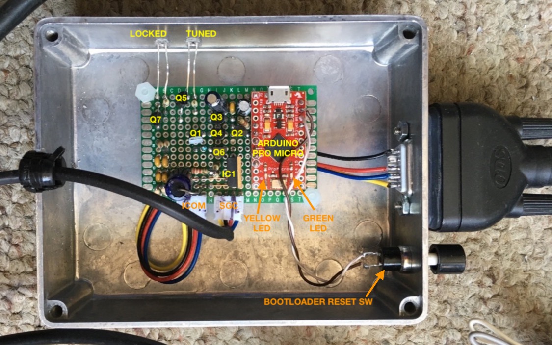
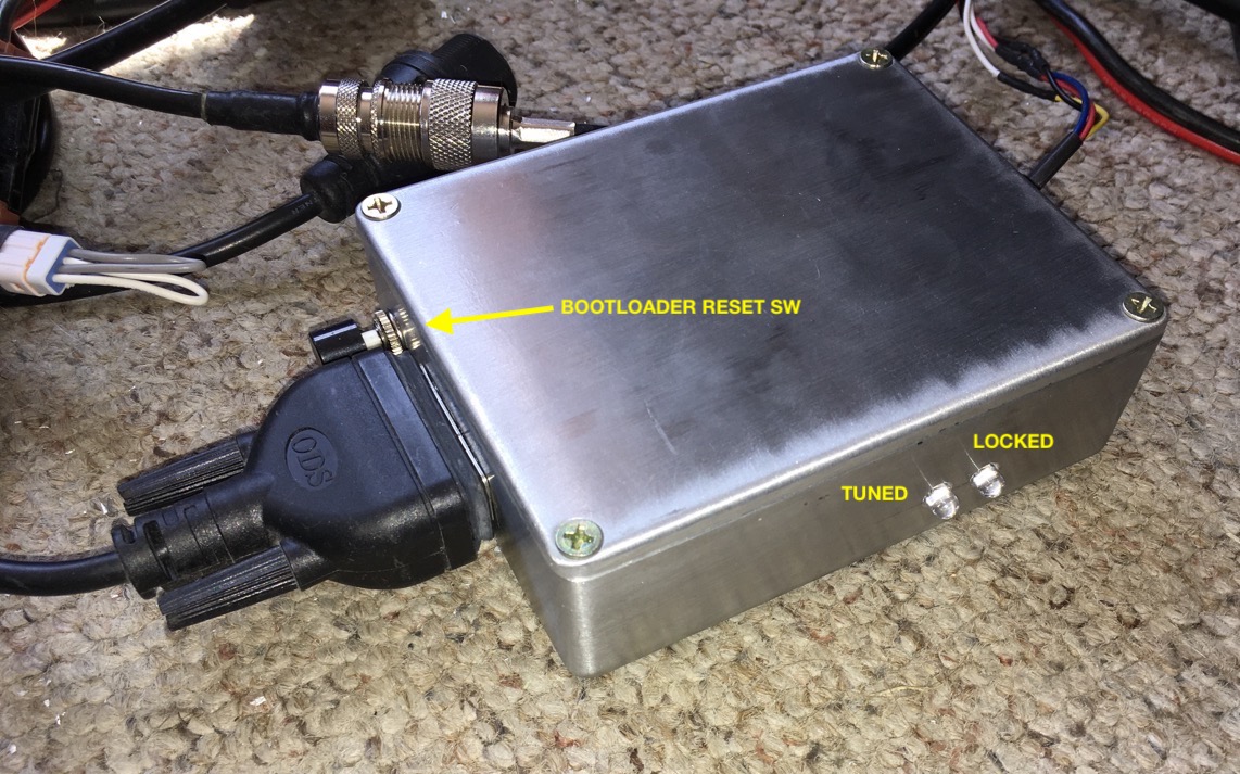
Construction Photos
Functional Validation
All operational validation was performed using a Saleae Logic
analyzer. The following signals were captured during each test:
-
START_H
-
KEY_H
-
LOCK_H
-
RESET_L
-
TUNED_H
Captured images showing execution sequences performed by the ICOM AH4 SGC TUNER PROTOCOL CONVERTER
are included in each of the validation sections below:
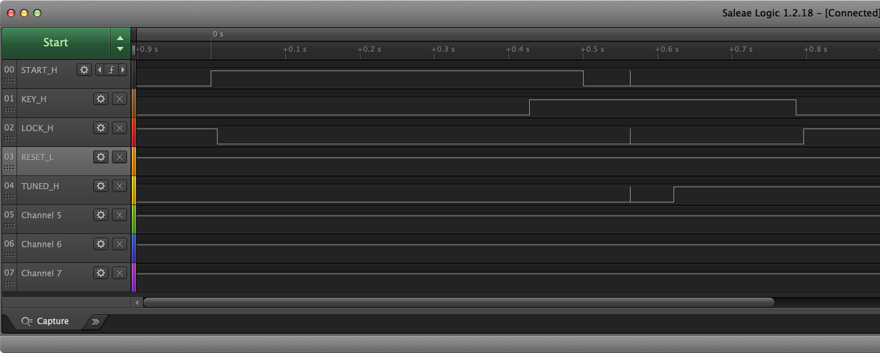
Successful Normal Tuning Cycle
A normal tuning cycle was initiated with a tuner load that is within the operational limits of the
SGC SG-230 auto-tuner. The
transciever asserts the START signal to start the auto-tune sequence. The
protocol converter responds to the START signal by unlocking the tuner, then asserts the KEY signal
to the transceiver, and after the tuner indicates TUNED, negates the KEY line and then LOCKS the
tuner.
Note that some RFI is present in the trace between 5 and 6 seconds. This is suspected to be due to
running the protocol converter outside of a metal enclosure and in close proximity to the antenna.
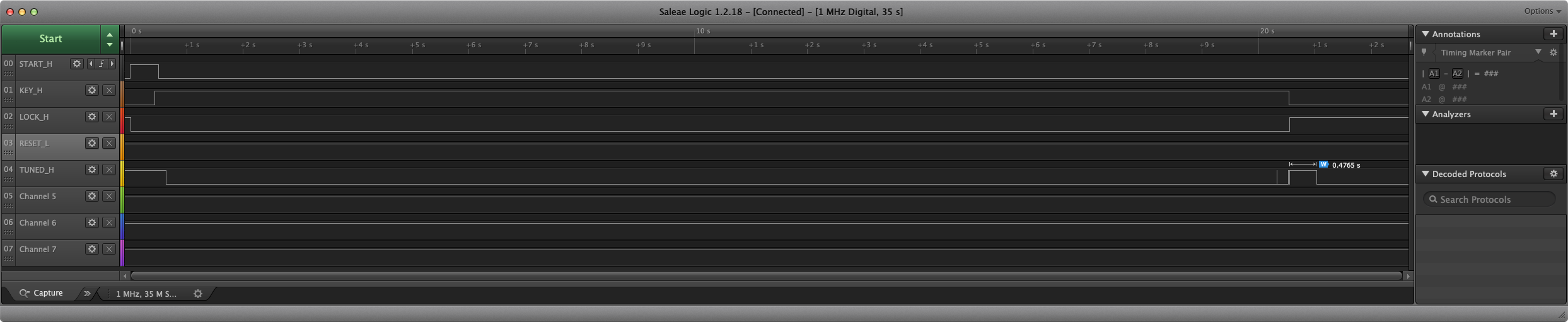
Unsuccessful Normal Tuning Cycle (AH4 Failure)
A normal tuning cycle was initiated with a tuner load that is outside the operational limits of the
SGC SG-230 auto-tuner (i.e. no antenna).
With this configuration, it was not possible to cause the
Icom IC-F8101-33
to detect a tune failure in that no terminating 200 millisecond assertion of START
was detected. A review of the Icom AH4 auto-tuner schematic shows no ability to assert the START
signal, which confirms that the START signal is only asserted from the transceiver. The root cause
of the transceiver not providing a terminating 200 millisecond assertion of START to indicate an
auto-tuning sequence failure is unknown. It is also unknown if this issue only occurs with the
Icom IC-F8101-33 transceiver.
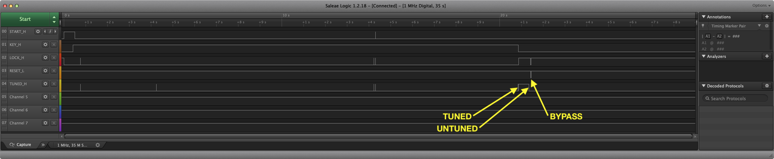
Unsuccessful Normal Tuning Cycle (SGC Failure)
A normal tuning cycle was initiated with a tuner load that is outside the operational limits of the
SGC SG-230 auto-tuner (i.e. no antenna).
When the SGC auto-tuner completes execution of the auto-tuning
sequence, and is unable to arrive at a tuned condition, the SGC auto-tuner will briefly indicate a TUNED
status, and then indicate an untunned status after 500 milliseconds. This is detected by the protocol
converter, resulting in the SGC tuner being placed into bypass mode.
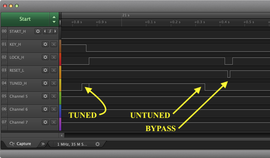
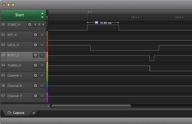
Tuner Bypass
Validation of tuner bypass mode, which is invoked by a short-press of the TUNE button on the Icom
Icom IC-F8101-33,
shows the transceiver assert the START signal for 70.89 milliseconds. This is recognized
by the protocol converter, which then unlocks the SGC auto-tuner, applies a RESET to the SGC auto-tuner
to place the tuner into bypass mode, and then asserts the LOCK signal to the auto-tuner.
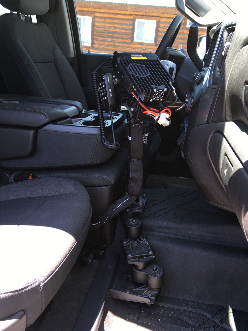
Installation Photos
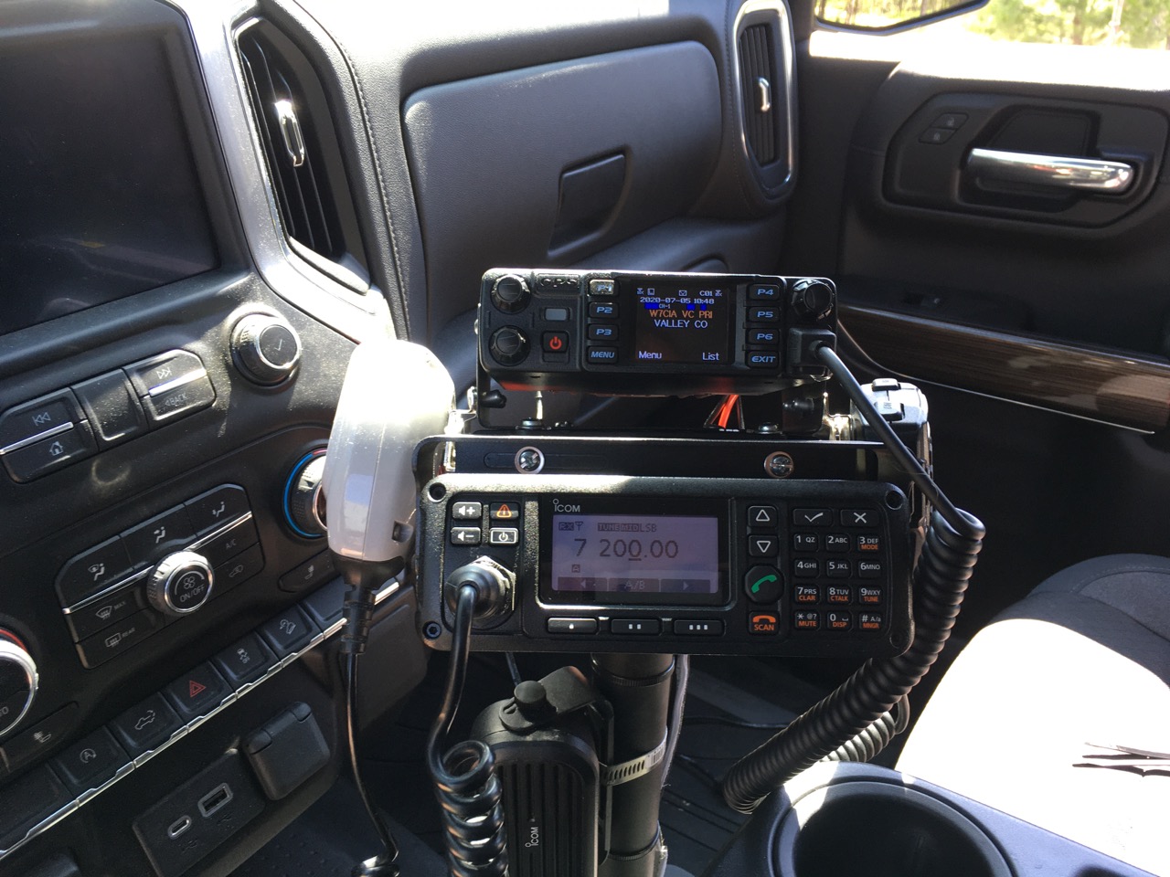
The Icom IC-F8101-33
control head is separated from the radio using the RMK-6 remote mounting kit and OPC-607 separation cable, and is then
remote mounted on a RAM Mounts pedestal system. The RAM Mounts pedastal system consists of a
RAM VB-203 No Drill Base for 2019 Chevy Silverado,
two Adjust-A-Pole Risers that are
used to both pivot the pedastal away from the passenger's knee and raise the pedastal above the
center hump, a 12" Lower Pole,
and a Tilt-N Turn 90° Bracket.
Note that the AnyTone AT-578UV transceiver that is mounted above the IC-F8101-33 control head is not
a component that comprises an HF capability in this mobile facility.
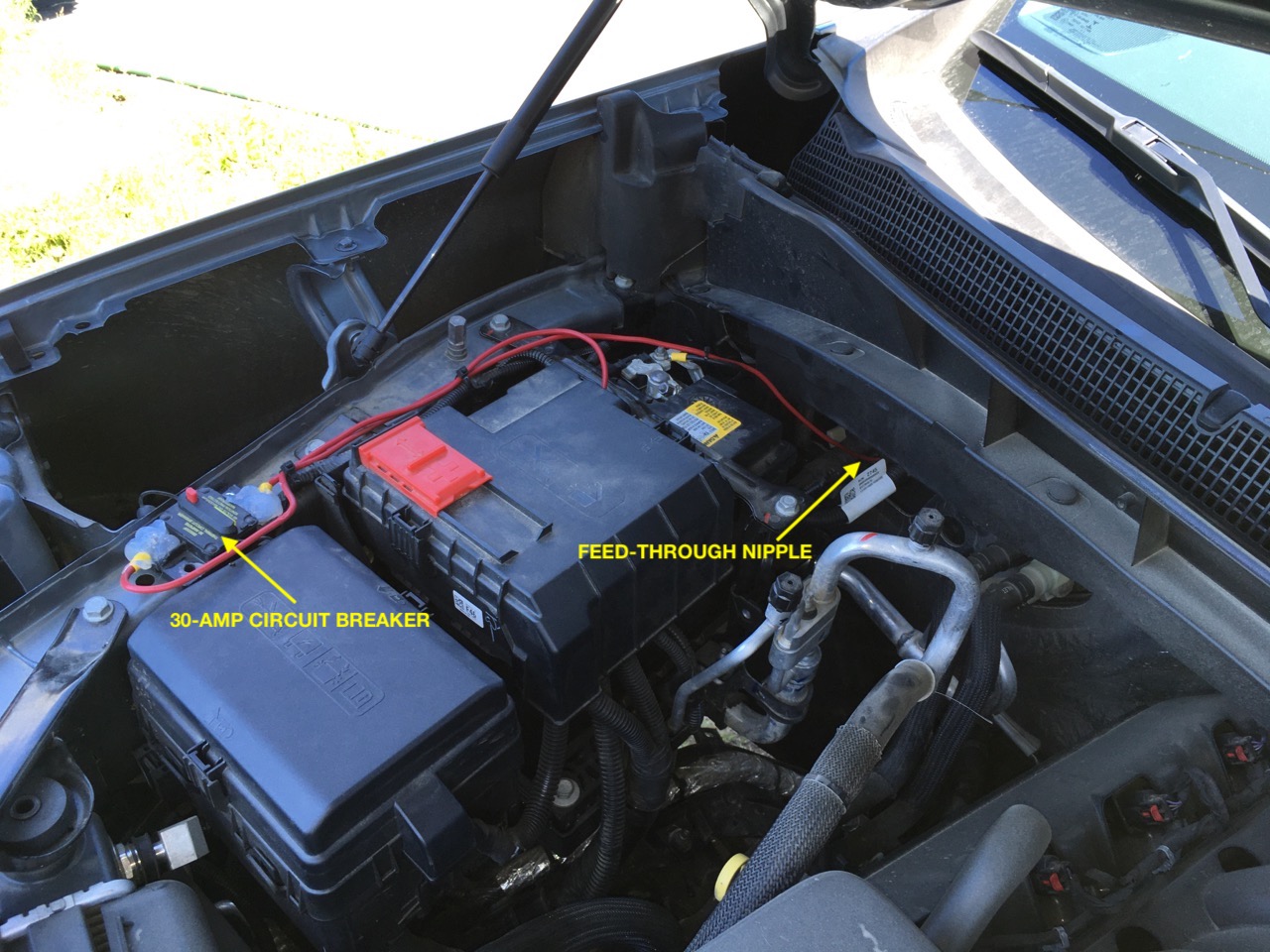
A nipple exists on the seal for the through-fire-wall cable assembly on the passenger side. This nipple
was cut and the radio power cable was fed through the opening. The power cable was then routed under
the passenger side kick panel and into the rear compartment. A 30-amp circuit breaker is installed on the positive lead.
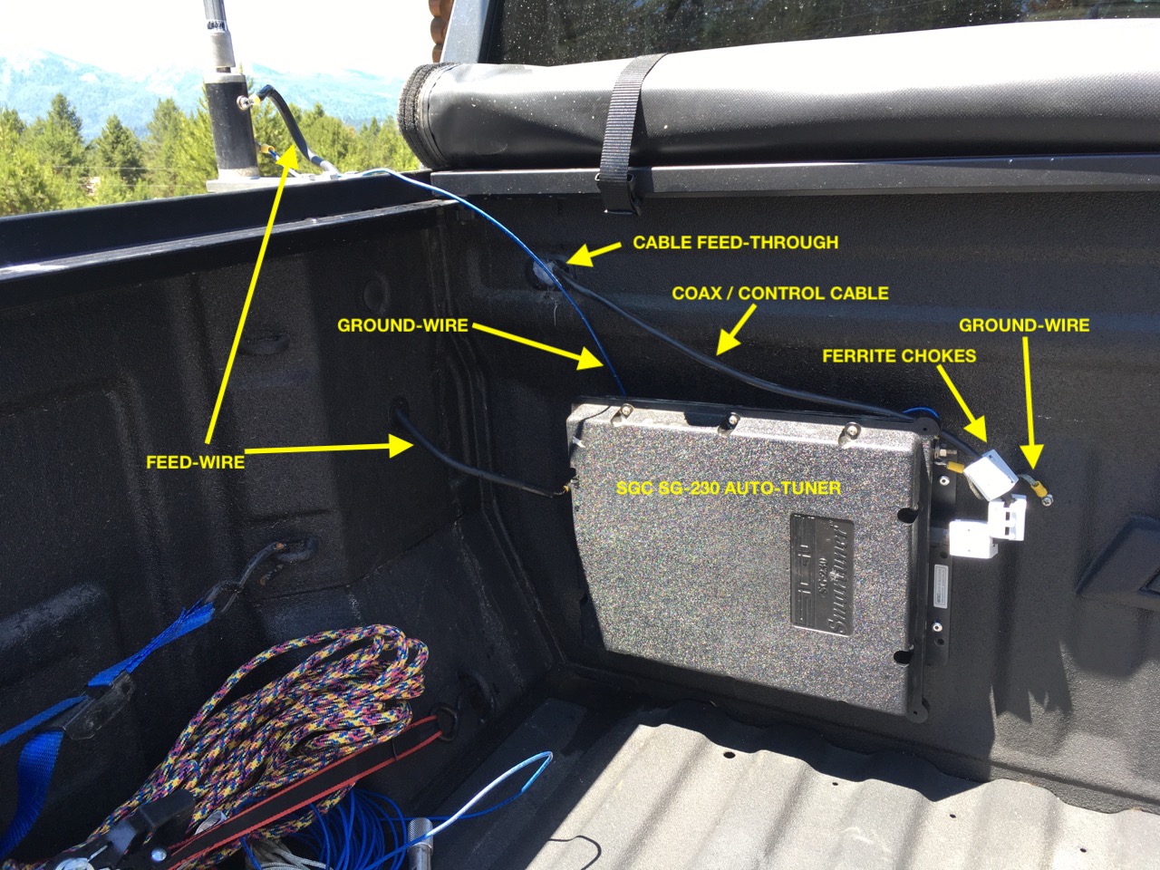
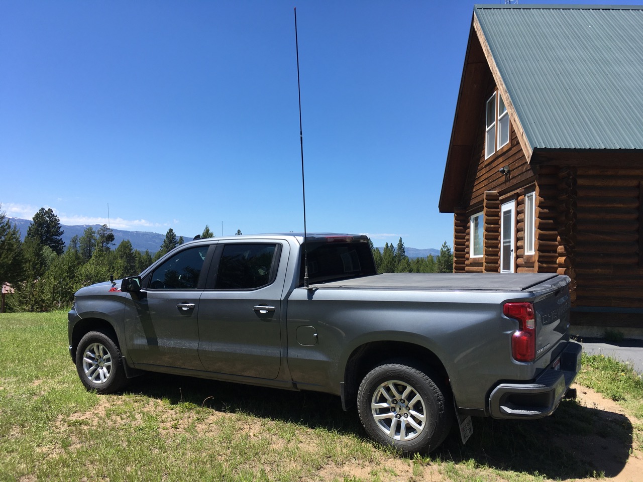
The SGC SG-230 Auto-Tuner is
riveted to the forward wall of the truck bed. A plastic feed-through was located at the front of the
bed on the driver's side. A 3/4 inch hole was drilled to accommodate
the SGC SG-230 auto-tuner feed-line / control cable.
To reduce coupling, the feed wire between the SG-230 auto-tuner and the antenna base must not lay flat
on the surface of the truck bed. The feed wire is routed at 90° to the vertical wall of the stake
pocket, using a plastic gasket, and then vertically out of the top of the stake pocked. A parallel
wire routing that layed flat on the truck bed resulted in extremely poor performance, with a proper
tuning solution not being available on many frequencies. This was resolved with the 90° routing
of the feed wire.
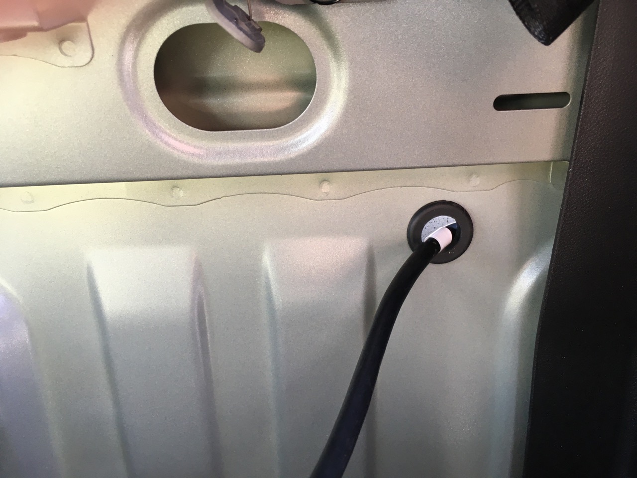
A 1-inch hole was drilled at the rear of the cab on the driver's side, and a 3/4 inch grommet was installed. The
SGC SG-230 feed-line / control cable was fed through
the grommet, leaving approximately 8 inches of cable in a strain relief loop between the cab and the bed. Generous
amounts of silicon seal were used on both cable feed-throughs.
Conclusion
Before disclosing the evaluation of the mobile HF facility while using the AH4 SGC auto-tuner protocol
converter, it is probably best to disclose the operational steps required to move frequency / channel
while using the SGC Lock circuit.
When using the SGC Lock circuit, changing frequency / channel on a transceiver that does not have any
auto-tuner support, or where the auto-tuner support requires handshaking signals between the auto-tuner
and the transceiver to be functional in order to use the auto-tuner user interface on the transceiver,
requires the following ordered steps:
-
Change the channel or frequency the transceiver
-
Manually unlock the SGC auto-tuner
-
Change the transceiver to CW mode
-
Change the transceiver power level to 10-watts
-
Key the transmitter
-
Wait for the SGC Lock circuit to indicate either a TUNED state (indicated by a solid ilumination
of the TUNED LED), or a failed tuning sequence (indicated by a flashing or solid OFF illumination
of the TUNED LED).
-
Unkey the transmitter
-
Manually lock the SGC auto-tuner
-
Set the transceiver power level back to its operational level
-
Set the transciever operating mode (typically Upper or Lower Side-Band)
With the AH4 SGC Protocol Converter, the steps required to change frequency / channel are reduced to:
-
Change the channel or frequency the transceiver
-
Push the TUNE button on the transceiver, holding the TUNE button in until a side-tone is heard, and
then release the TUNE button.
-
Wait until the side-tone stops
-
Verify the TUNED status by observing the TUNED LED
With the IC-F8101-33 transceiver, the transceiver can be configured to initiate an auto-tune sequence
by depressing the Push-To-Talk (PTT) after changing frequencies. If configured in this manner, step 2
in the AH4 SGC Protocol Converter sequence immediately above is replaced by pressing the PTT until a
side-tone is heard, and then immediatelly release the PTT.
Note that with the IC-F8101, an auto-tune sequence initiated from the transciever (i.e. TUNE button or
PTT TUNE) will automatically reduce power to 10-watts, switch modes to transmit a pure carrier, initiate
the auto-tune sequence at the reduced power level and proper mode, and then restore the operating mode
and power level at completion of the auto-tuning sequence.
The AH4 SGC Protocol Converter significantly reduces the complexity and number of tasks required to
successfully change channels / frequency and arrive at a successful auto-tuner tuning solution. From
a user interface perspective, the radio operator interacts directly with the transceiver, and the
operation of the SGC auto-tuner becomes seamless. Comparatively, the manual process of using the SGC
Lock circuit is both complex and requires a large number of steps to execute, resulting a significant
diversion of attention.
Ray Montagne (W7CIA)
UPDATES:
A second unit has now been installed to interface an Icom IC-7100 to an
SGC SG-237 auto-tuner belonging to Mel Di Carli (KG7LQQ). The same simple tuning experience occurs on
this installation with the exception that the IC-7000 does not emit a side-tone during
tuning, but provides and LED indication with equivalent function to the side-tone in
indicating initiation and comletion of the auto-tune sequence. This installation was
completed on 8 Dec 2020. Mel reports "TBD."
73 de W7CIA