IC-F8101 - Interfacing a SignaLink USB
A SignaLink can be interfaced through the female 15-pin DSUB accessory connector that is available
on a dongle from the rear of the IC-F8101.
A 15-pin, 3-row D-Sub Male connector
is needed to construct the interface cable. A Connector
Shell should be installed to protect the cable connections.
The SignaLink has an RJ-45 connector, which is the same connector used on an Ethernet cable. The
easiest way to interface the SignaLink to the IC-F8101 Accessory connector is to remove one connector
from a short ethernet cable (ie. 3 to 6 feet long), strip each of the eight wires on the end of the
cable where the connector was removed, insert the other end of the cable to an opened up SignaLink,
use an ohm meter to determine which color coded wires connect to the four signals on the SignaLink
(ie. SPK, MIC, PTT and G).
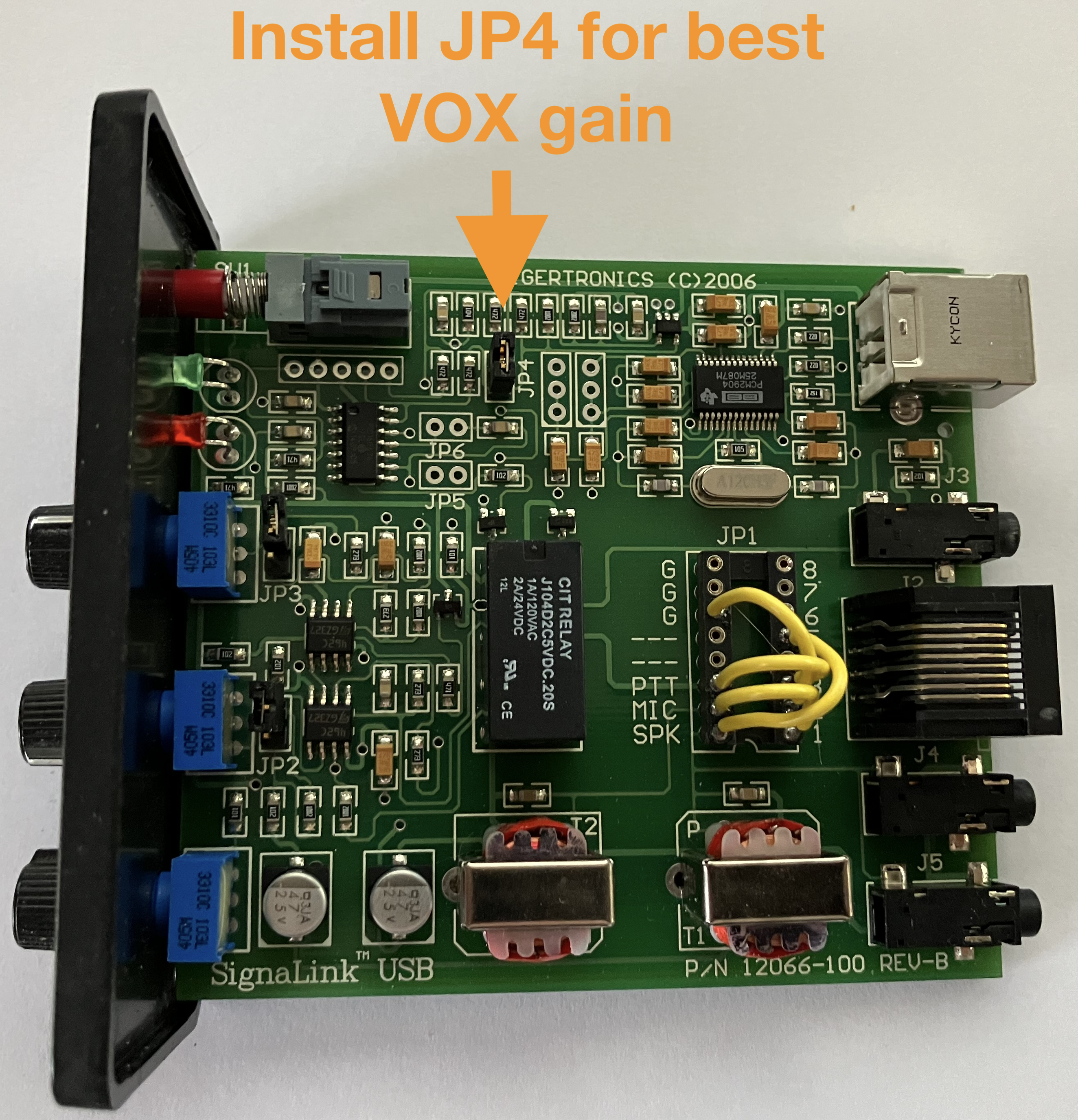
The following procedure strives to avoid modifying the SignaLink JP1 jumper block in the assumption
that JP1 is configured to also support another radio. The goal is to not break support for that other
radio.
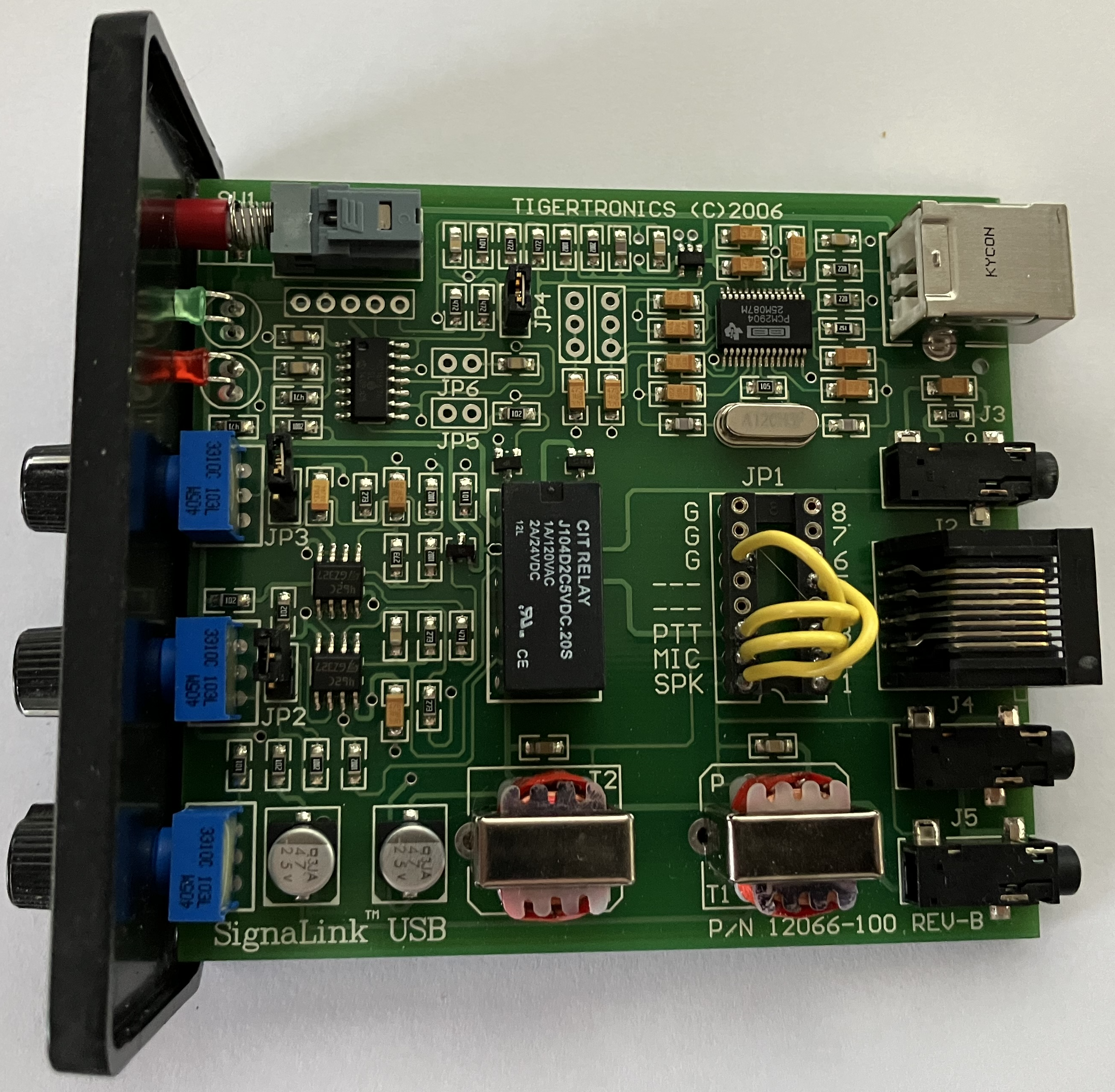
The following is an example of interfacing a SignaLink. Your JP1 jumper block in the SignaLink may be
configured differently than shown in this example and may result in a completely different wiring
configuration than shown in this example. You will need to determine the ethernet cable wire color
codes for the SignaLink signals for your specific SignaLink configuration. This example intends to
disclose only the process of determining the wiring configuration.
In the example configuration, the JP1 jumper block in a specific SignaLink.
The following is a schematic of the JP1 jumper block from the photo above.
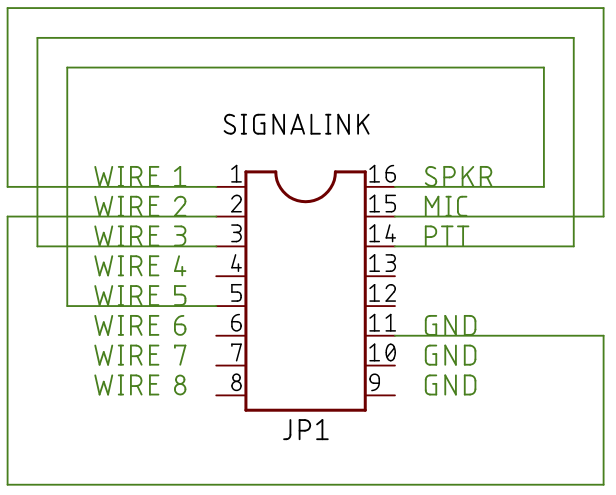
Where wires 1 through 8 are the pins on the RJ-45 connector on the SignaLink, the schematic shows:
-
The SPK (ie. receiver audio output) is connected to Wire 5.
-
The MIC (ie. transmitter audio input) is connected to Wire 1.
-
The PTT (ie. transmitter key line) is connected to Wire 3.
-
G (ie. ground) is connected to Wire 2.
A short ethernet cable, of 3 to 6 feet in length, is prepared by cutting the RJ-45 connector off
of one end of the ethernet cable. Remove 2 inches of the outer insulation from the ethernet cable
on the end where the RJ-45 connector was removed to expose the eight signal wires. Strip 1/4 inch
of insulation off of each of the eight color coded signal wires. Then plug the RJ-45 connector at
the other end of the cable into the Radio connector on the SignaLink.
Ensure that the USB connector is disconnected from the SignaLink!
Referencing the side of the JP1 jumper block in the SignaLink, where the signal names (ie. G,
PTT, MIC, SPK) are silk-screened onto the printed circuit board, use an ohm meter
to determine which of the four signals is connected to which of the eight color coded signal wires,
recording the color codes of the wires against the signal names.
In this example, the following table shows the wire color codes and their relationship to the signal
names on the SignaLink JP1 jumper block:
|
SIGNAL NAME
|
WIRE CLOR CODE
|
|
G
|
ORANGE
|
|
PTT
|
WHITE / GREEN
|
|
MIC
|
WHITE / ORANGE
|
|
SPK
|
WHITE / BLUE
|
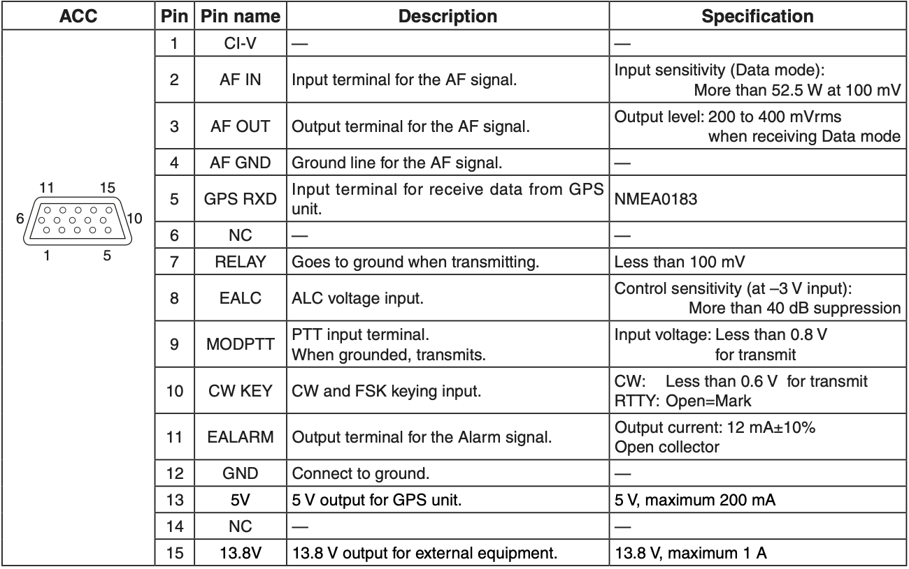
The four wires, defined by their signal names and wire color code in the table above, are then wired
to the DSUB-15 male accessory connector as follows:
|
SIGNAL NAME
|
WIRE COLOR CODE
|
DSUB-15 PIN
|
DSUB-15 NAME
|
|
G
|
ORANGE
|
12
|
GROUND
|
|
PTT
|
WHITE / GREEN
|
9
|
MODPTT
|
|
MIC
|
WHITE / ORANGE
|
2
|
AF IN
|
|
SPK
|
WHITE / BLUE
|
3
|
AF OUT
|
For your configuration, substitute the appropriate wire color codes that you have determined by
testing the continuity between the eight color coded wires and the SignaLink JP1 jumper block with
an ohm meter as previously described.
Fill in the wire color codes for your SignaLink JP1 configuration to determine how to wire the DSUB-15 connector:
|
SIGNAL NAME
|
WIRE COLOR CODE
|
DSUB-15 PIN
|
DSUB-15 NAME
|
|
G
|
|
12
|
GROUND
|
|
PTT
|
|
9
|
MODPTT
|
|
MIC
|
|
2
|
AF IN
|
|
SPK
|
|
3
|
AF OUT
|