COMMS Working Group
Hawaii
Alaska
Pacific
Mountain
Central
Eastern
Puerto Rico
UTC
Guam
HF Magnetic Loop - 20m through 10m With Remote Tuning Control
Table Of Contents


HF Magnetic Loop
20m Through 10m With Remote Tuning Control

By Ray Montagne (W7CIA)


Introduction

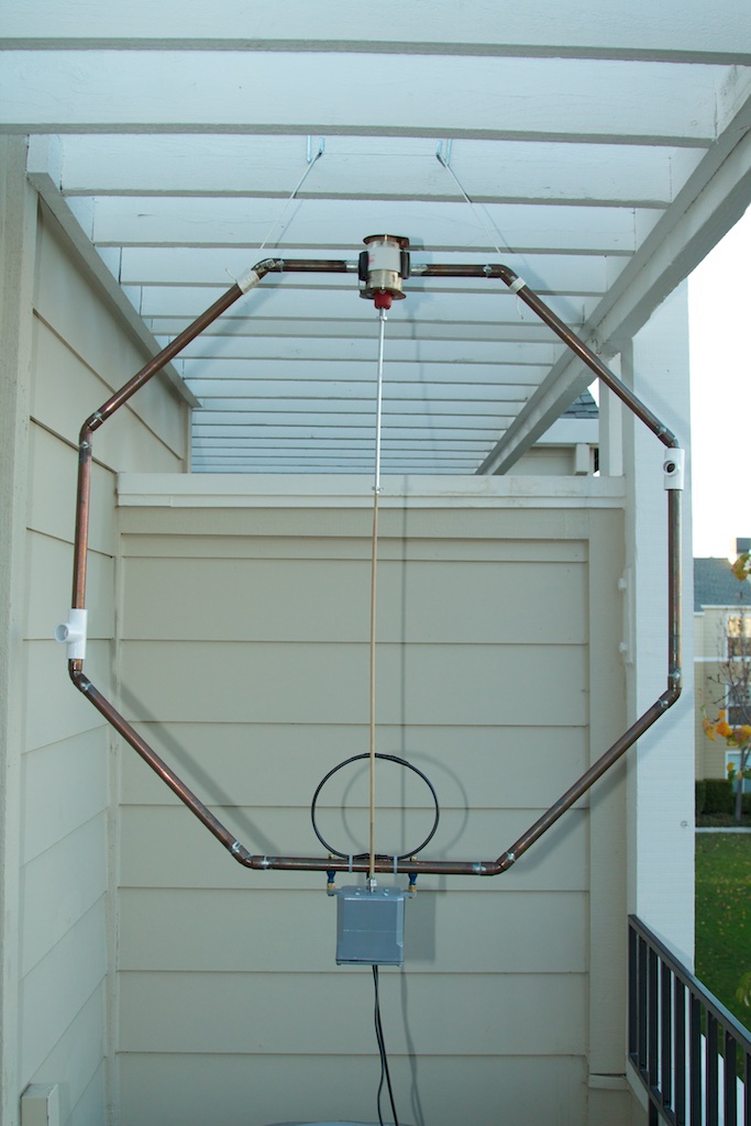
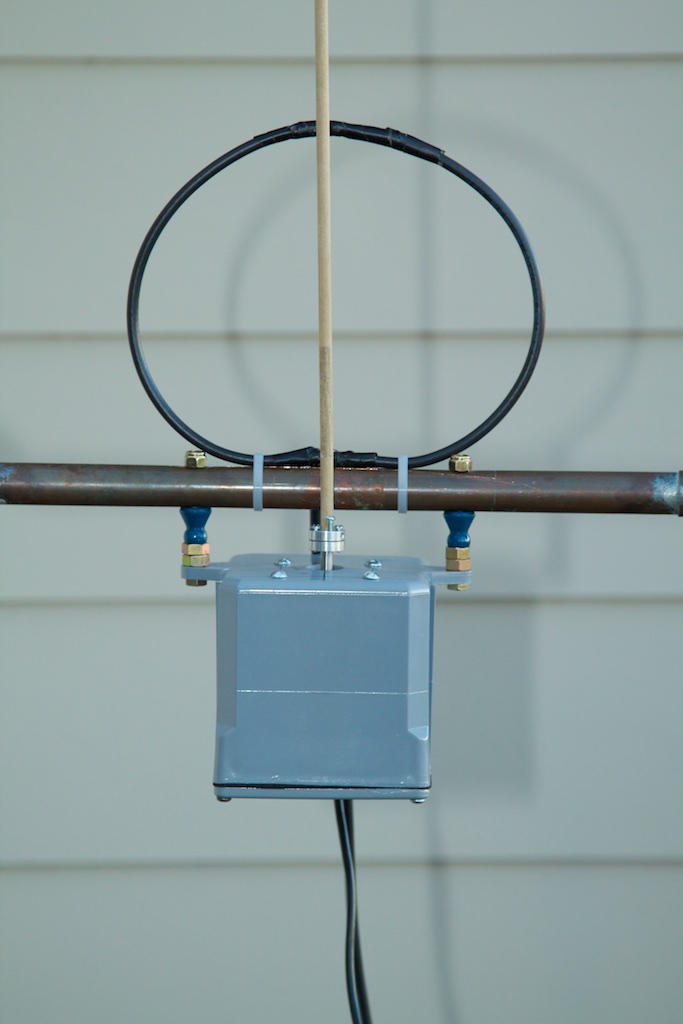
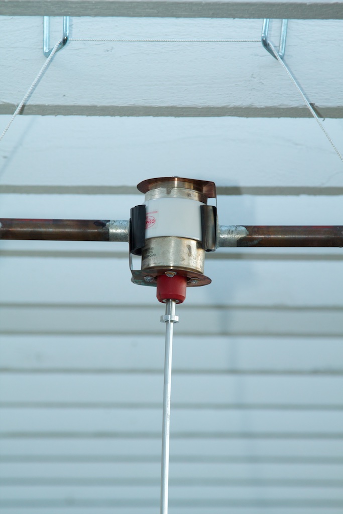
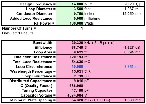
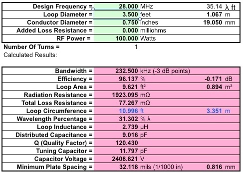
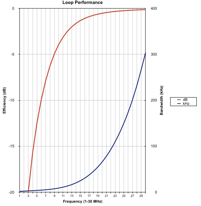
This antenna was built when an extremely small antenna was required for operation on 20-meters through 10-meters, using a 100-Watt transceiver, at a location with antenna restrictions. The antenna was used to work a great deal of DX on 20m and 15m, using the JT65-HF mode. Of course this antenna is not as efficient as a full sized antenna, but where a compromise antenna is needed for 20m through 10m, the Magnetic Loop offers good performance for what it is (and certainly much better performance than a mobile antenna could ever achieve).


Overview

Performance Calculations

The AA5TB calculator produced the following at 14 MHz:


The AA5TB calculator produced the following at 28 MHz:


The AA5TB calculator produced the following at performance curves:


Tuning Process

The tuning process has the joystick deflected, with a fairly large deflection, until peak noise is heard in the receiver. Then, using low power, small deflections of the joystick are made while observing the reflected power until the minimum reflected power is observed. Once the tuned position was determined, that position can be stored using the buttons, and recalled later with a single button press. With only four-buttons on the Joystick Shield Kit, there is limited ability to store tuned positions. This was adequate for me as I was only storing the JT65-HF frequencies (i.e. 14076 kHz, 21076 kHz, and 24917 kHz [NOTE: I had an S9 + 20 dB noise floor on the 17m band at the location where I used this antenna, and did not use the 17m band]).


Power Limits

Power levels above 100-Watts will result in much higher voltages across the capacitor. If you are thinking of running higher power levels, don't. If you want to know why, use the AA5TB calculator, inputing a higher power-level, and then look at the voltages that are generated across the capacitor at the top of the loop. Vacuum variable capacitors are not cheap. The model I used had a voltage limit of 10 KV at the 10 pf end of the tuning, and 6 KV at the 60 pf end of the tuning, and cost somewhere around $60. This loop generates just over 4KV at the capacitor when at the 47.19 pf tuning point at 14000 kHz. Arcing can destroy the Vaccum Variable Capacitor. A higher voltage rating is going to cost more. Best to just keep it at or below 100-Watts.


Schematics

A schematic of the Arduino Uno can be downloaded by clicking here.

A schematic of the SparkFun Joystick Shield Kit can be downloaded by clicking here.

A schematic, which shows the ULN2003 Darlington Transistor driver that is used to drive the stepper motor is shown below. A .pdf version can be downloaded by clicking here.


Stepper Motor Driver Schematic

Note that +12 VDC is not carried over the shield header pins from the Arduino Uno to the Joystick Shield. The +12 VDC can be brought over with a wire that is attached to the +VDC power supply connector on the Arduino Uno by soldering a wire on the bottom of the Arduino Uno board.


Operational Notes

Download The Source Code

The source code can be downloaded by clicking here.


Recommendations For Improvement

Although the magnetic loop proved to be useful, and especially so in that no larger antenna could be used, there are areas that could be improved.

Good luck and have fun, Ray Montagne (W7CIA)