|
Icom AH4 Auto-Tuner Protocol Emulator for the MFJ-994BRT Remote Auto-Tuner |
|
|
Version 0.03
25 November 2022 |
|
|
| Copyright © 2022 Raymond B Montagne All rights reserved. |
| COMMS Working Group |
| Hawaii |
Alaska |
Pacific |
Mountain |
Central |
Eastern |
Puerto Rico |
UTC |
Guam |
|
Icom AH4 Auto-Tuner Protocol Emulator for the MFJ-994BRT Remote Auto-Tuner |
|
|
|
Version 0.03
25 November 2022 |
|
|
| Copyright © 2022 Raymond B Montagne All rights reserved. |
A pdf version of this article can be downloaded by clicking HERE.
BSD-3 Clause License
Copyright © 2022 Raymond B Montagne All rights reserved.
Redistribution and use in source and binary forms, with or without modification, are permitted provided that the following conditions are met:
THIS SOFTWARE IS PROVIDED BY THE COPYRIGHT HOLDERS AND CONTRIBUTORS "AS IS" AND ANY EXPRESS OR IMPLIED WARRANTIES, INCLUDING, BUT NOT LIMITED TO, THE IMPLIED WARRANTIES OF MERCHANTABILITY AND FITNESS FOR A PARTICULAR PURPOSE ARE DISCLAIMED. IN NO EVENT SHALL THE COPYRIGHT HOLDER OR CONTRIBUTORS BE LIABLE FOR ANY DIRECT, INDIRECT, INCIDENTAL, SPECIAL, EXEMPLARY, OR CONSEQUENTIAL DAMAGES (INCLUDING, BUT NOT LIMITED TO, PROCUREMENT OF SUBSTITUTE GOODS OR SERVICES; LOSS OF USE, DATA, OR PROFITS; OR BUSINESS INTERRUPTION) HOWEVER CAUSED AND ON ANY THEORY OF LIABILITY, WHETHER IN CONTRACT, STRICT LIABILITY, OR TORT (INCLUDING NEGLIGENCE OR OTHERWISE) ARISING IN ANY WAY OUT OF THE USE OF THIS SOFTWARE, EVEN IF ADVISED OF THE POSSIBILITY OF SUCH DAMAGE.
My station includes an Icom transceiver driving an Elecraft KPA-500 amplifier and an Elecraft KAT-500 auto-tuner. I recently installed an Inverted-L antenna that is located more than 200-feet from the radio installation. Using the KAT-500 auto-tuner to match the Inverted-L with over 200-feet of LMR-400 feed-line resulted in an inability to tune the antenna on a large number of frequencies.
Operationally, the main goal is to achieve a high-power Automatic Link Establishment, using ION2G, primarily supporting operation on NTIA channels that are outside of Part 97 frequency allocations.
My past experience with the Inverted-L demonstrated that when coupled with a remote auto-tuner, located at the base of the vertical segment of the antenna, there were no frequencies that the auto-tuner could not produce a proper impedance match. My prior experience was with an LDG RT-100 ATU, a 100-watt ATU that powers the ATU through the coaxial feed-line via a Bias-T. LDG had manufactured a higher power remote ATU, the RT-600 with a 600-watt rating. Unfortunately, the RT-600 ATU is no longer available.
The search for a remote ATU kept landing on MFJ. I have not been a big fan of MFJ products, but decided to give the MFJ-994BRT a go. Like the LDG RT-600, the MFJ-994BRT is rated for 600-watts power, and this provides some adequate headroom above the KPA-500 amplifier's 500-watt output.
No matter which remote ATU I chose, there are some significant differences between the Elecraft KAT-500 ATU and the available remote ATU offerings. Among these differences are the following critical features found in the Elecraft KAT-500 / KPA-500 configuration:
Lacking the above features that are inherent with the Elecraft configuration, using a remote auto-tuner reverts to a largely manual process that requires the following steps:
Comparing this to the KPA-500 / KAT-500 configuration required a single push of the TUNE button on the KAT-500 auto-tuner to achieve proper operation after changing frequency.
The increased operating complexity with the remote auto-tuner is undesirable. If using digital communications that are frequency agile, such as Automatic Link Establishment, the increased operational complexity is unacceptable.
What is needed is an emulation of the Icom AH4 auto-tuner protocol, with the addition of blocking the key-line to the KPA-500 amplifier during a tuning sequence, to restore an automated one-touch operation.
Icom AH4 Normal Tuning
The Icom AH4 protocol is implemented with two signals, START and KEY. A normal AH4 auto-tuning sequence occurs as follows:
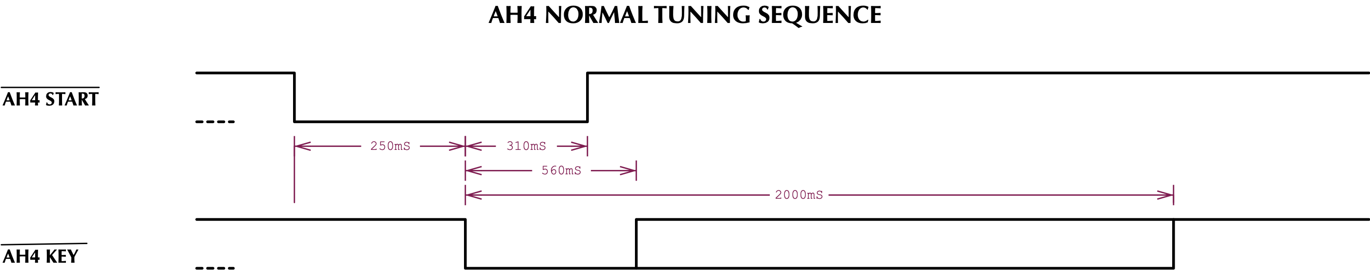
To emulate the AH4 protocol, a microcontroller is needed to model the state transitions that occur with the AH4 protocol signals, and an ability to determine when the VSWR has stabilized so that the KEY request to the transceiver can be terminated. An Arduino Pro Mini is used to implement the AH4 protocol state machine, and a Fox Delta FD-HFB3-1213 Balanced Bridge is interfaced to the Arudino to provide VSWR sensing.
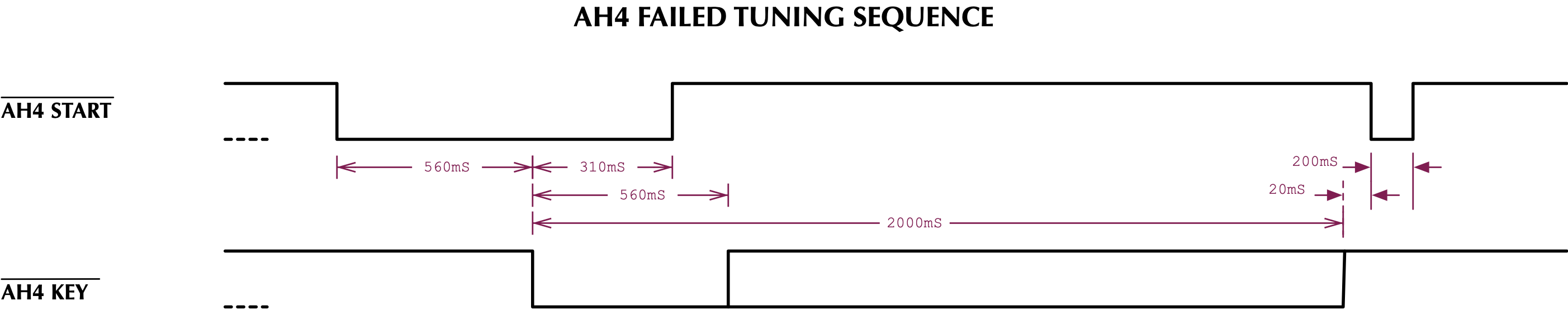
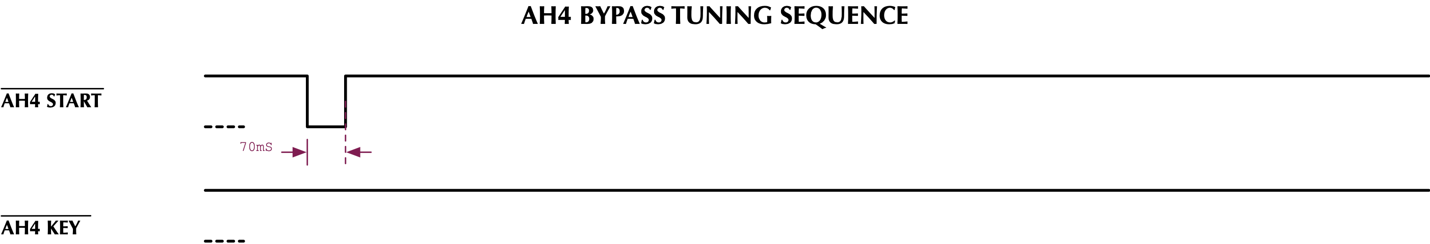
NOTE: This project is emulating only the normal AH4 tuning protocol. Not supported are the AH4 protocols for placing the auto-tuner into BYPASS mode, or the AH4 protocol for indicating an auto-tuning error (ie. when no tuning solution was determined). There is no method of determing an auto-tuning error from the MFJ-994BRT remote auto-tuner, other than possibly an unacceptable VSWR. The non-remote version of the MFJ-994 does support a BYPASS mode, but with the control board buttons inside the case of the MFJ-994BRT remote tuner, placing the auto-tuner into BYPASS mode is only possible by removing the DC power to the remote tuner (which is best done with the power switch on the BIAS-T device).
Icom AH4 Normal Tuning - Failed Tuning
Icom AH4 Bypass Tuning
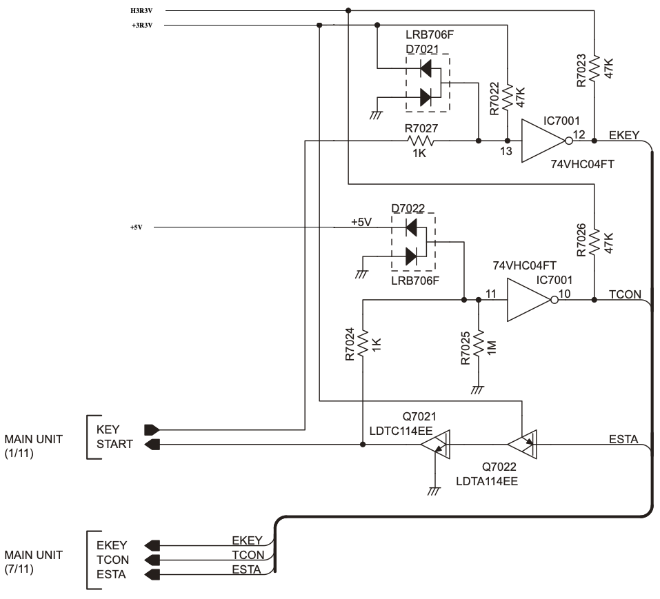
The Icom IC-7610 AH4 Tuner Interface has a weak pull-down termination (R7025) on the START signal. The START signal has a strong pull-up that is located in the auto-tuner. If no auto-tuner is present, the weak pull-down on the START signal will result in a low being presented to the TCON signal and the IC-7610 will then determine that no external auto-tuner is attached during power-on boot. If the START signal is read as high during the power-up boot of the IC-7610, via the TCON signal, the IC-7610 determines that an external auto-tuner is attached.
The IC-7610 provides a strong pull-up termination (R7022) of the KEY signal, an input to the IC-7610. The auto-tuner should provide a weak pull-down of the KEY signal, and should have the ability to read the state of the KEY signal. If the KEY signal is read by the auto-tuner, and a low is detected while the auto-tuner is not driving the KEY signal low, the auto-tuner should determine that the IC-7610 is powered off, and should wait for the KEY signal and the START signal to go high prior to responding to any low assertion of the START signal.
The 1KΩ series resistors (R7024 & R7027) on each of the AH-4 Signals limit the current through the clamping diodes (D7022 & D7021) that prevent the I/O signals from exceeding the signal levels specified by the I/O logic devices.
The auto-tuner/emulator should provide a strong pull-up termination of the START signal. This is necessary to overcome the weak pull-down in the IC-7610 for both signal termination and so that the IC-7610 properly detects the presence of the tuner during power-on boot.
The auto-tuner/emulator should provide a weak pull-down termination of the KEY signal. This is necessary so that the KEY SENSE signal properly indicates when the IC-7610 is not powered on, and is used to gate accepting an assertion of the START signal to only occur when the IC-7610 is powewred-on.
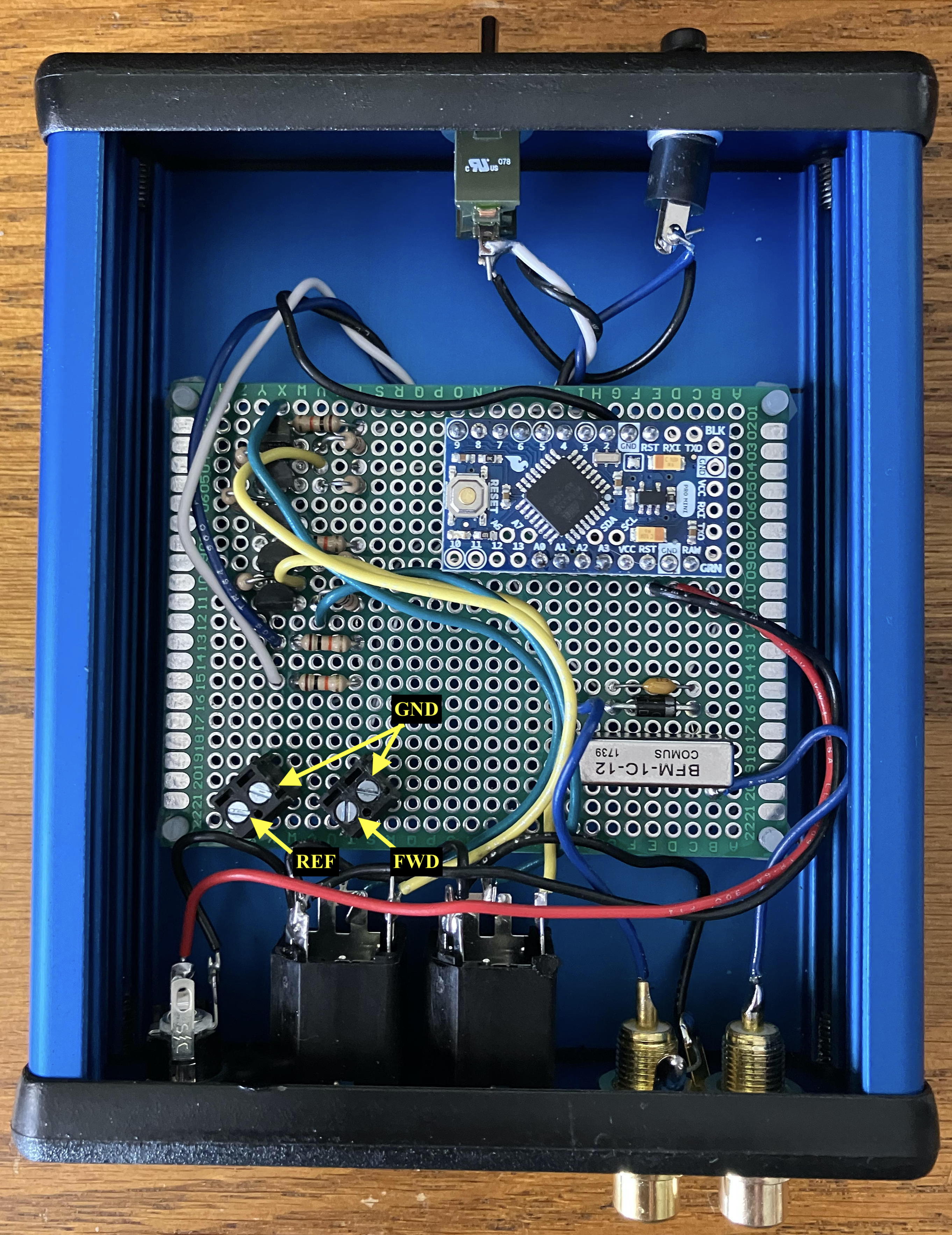
The Fox Delta FD-HFB3-1213 Balanced Bridge is available in kit form. The HFB-3 provides two adjustable outputs that represent a forward voltage and a reflected voltage. These outputs are adjustable and can be scaled to remain within the 0 to full-scale range of an analog to digital converter (ADC).
The following schematic depicts the Fox Delta HFB3 circuit. Note that this schematic corrects two errors on the schematic provided by Fox Delta, where the Forward and Reflected voltages were depicted as being routed off the top of the trim resistors. The corrected circuit has the Forward and Reflected voltages taken from the variable tap on the trim resistors. This error only appears on the schematic. The printed circuit board is implemented correctly.
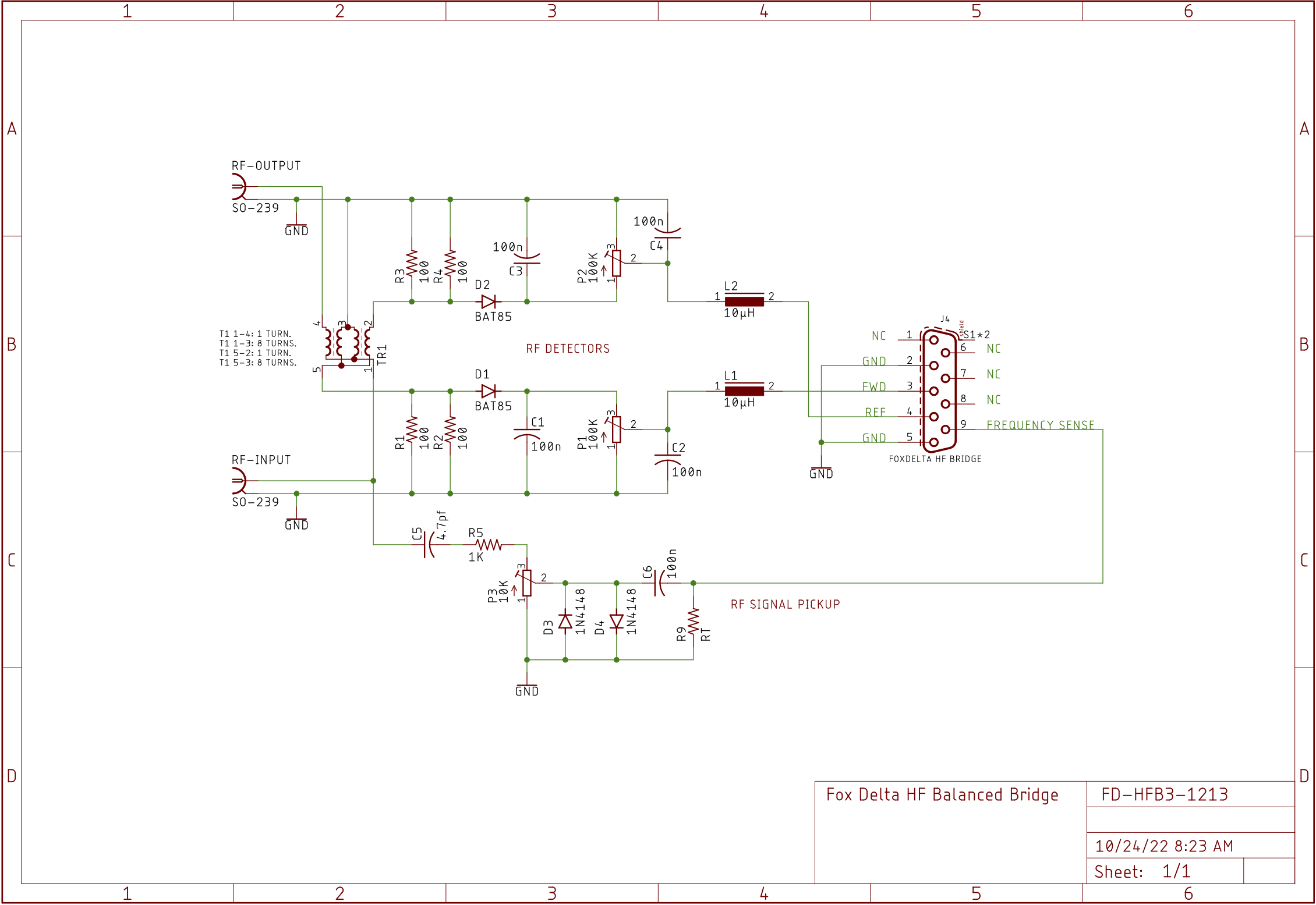
Calibration of the Fox Delta HFB3-1213 HF Balanced Bridge should be performed before connecting the HFB3 to the Arduino Pro Mini. Note that the HFB3 is limited to transmitters operating at 100-watts or less.
The following steps can be used to calibrate the HFB3 to produce Forward output voltage that is compatible with the 5-volt Arduino Pro Mini:
The following steps can be used to calibrate the HFB3 to produce Reflected output voltage that is compatible with the 5-volt Arduino Pro Mini:
Although not used in this project, the following steps can be used to calibrate the Frequency Sense output voltage:
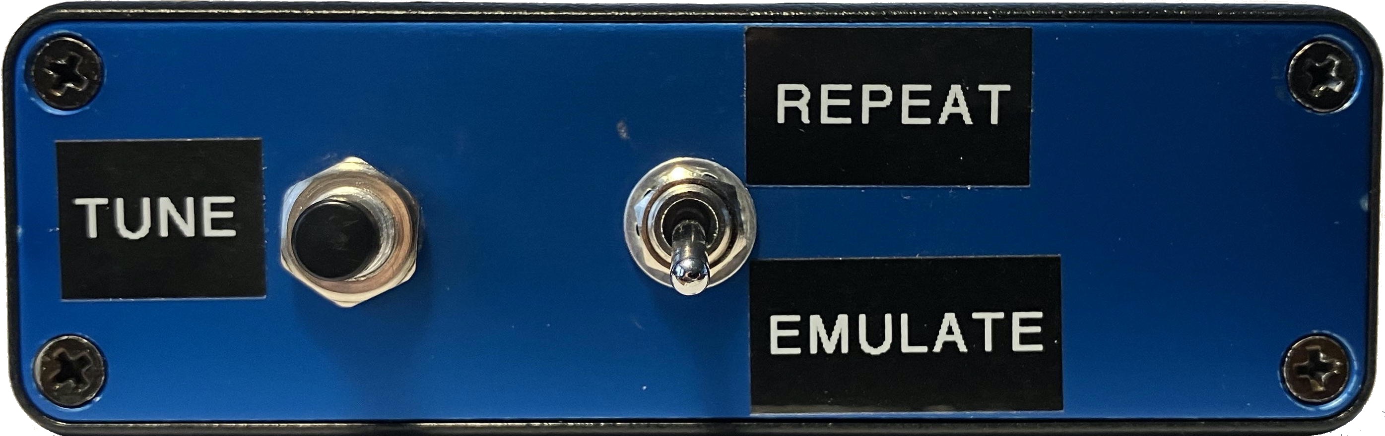
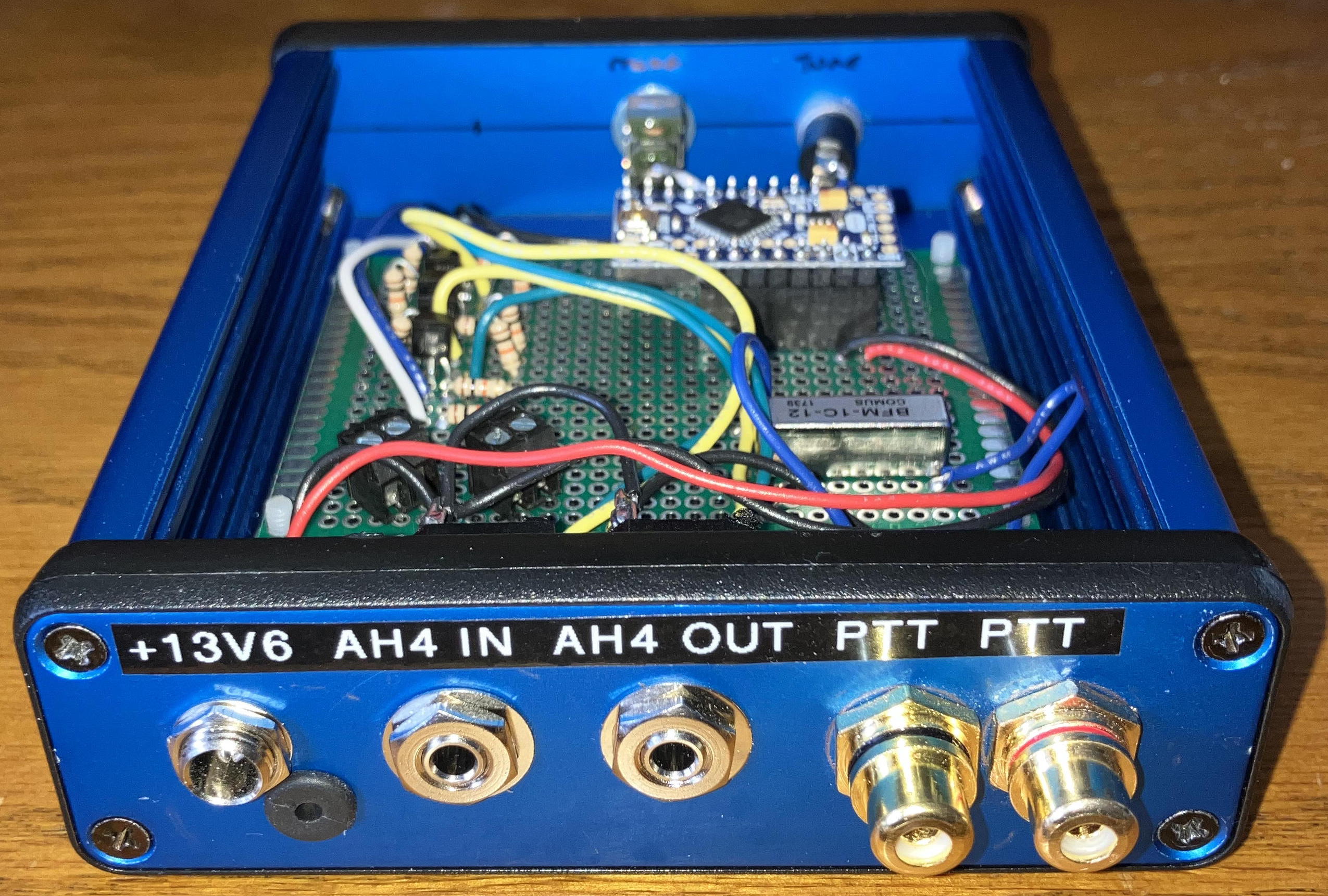
The AH4 Protocol Emulator includes the following features:
The Mode switch is used in a configuration that has another auto-tuner, such as an Elecraft KAT500, providing RF routing through antenna switches. In such a configuration, one antenna port/switch will route RF to the MFJ-994BRT Remote Tuner and the remaining ports/switches will route RF to other antennas. When the antenna port assigned to the MFJ-BRT994 Remote Tuner is selected, the KAT500 must be placed into BYPASS mode and the AH4 ATU Protocol Emulator MODE switch must be placed into MODE A / EMULATION. When another antenna port is selected, that does not route RF to the MFJ-994BRT, the AH4 ATU Protocol Emulator MODE switch must be placed into MODE B.
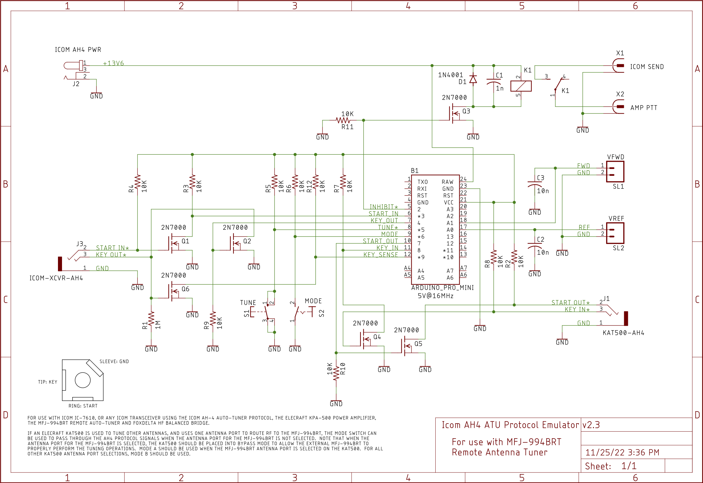
When in MODE B, the AH4 ATU Protocol Emulator will enable the amplifier keying and act as a repeater for the AH4 protocol (ie. AH4 START from the transceiver is forwarded to the KAT500, and AH4 KEY from the KAT500 is forwarded to the transceiver). The AH4 ATU Protocol Emulator TUNE button is disabled in MODE B.

The source code is written in the C programming language and can be compiled with the Arduino IDE. Source code tab-stops are based on a 4-character per tab-stop setting.
The source code implements a state machine that provides the AH4 protocol emulation. State machine execution is as follows:
WAIT RADIO POWERUP
This is the initial state. Should the KEY SENSE signal be sensed low when the KEY signal is not being driven by the AH4 Emulator, execution will return to this state under the assumption that the transceiver has been powered down.
When the KEY SENSE signal indicates that the transceiver has powered up, the state machine will advance to the IDLE state.
IDLE
The IDLE state detects an assertion of the START signal to start the tuning process. If START is detected, this state will block the keying of the KPA-500 amplifier. A timer is then primed to produce the delay between START assertion and KEY assertion before advancing to the POST START DELAY state.
Alternatively, a manual tuning sequence can be initiated by depressing the TUNE button. Like a START initiated tuning sequence, , this state will block the keying of the KPA-500 amplifier. A timer is then primed to produce the delay between START assertion and KEY assertion before advancing to the POST START DELAY state.
POST START DELAY
This state runs the delay timer to terminal count before advancing to the ASSERT KEY state.
ASSERT KEY
If the START signal remains asserted, or manual tuning was started via pressing the TUNE button, this state will assert the KEY signal. The timer is then primed to support a delay to allow the transceiver transmitter to key before checking for a tuning solution in the next state. The state is then advanced to the Wait For Transmit RF state.
If the START signal is not asserted and the tuning was not started manually, the state advances to the Wait For Tune Button Release state.
WAIT FOR TRANSMIT RF
This state runs the timer down to terminal count while sampling RF to determine if the transmitter has keyed. If the transmitter RF is detected before the timer reaches terminal count, the state is advanced to the Wait For Stable VSWR state.
If no transmitter RF is detected and the timer reaches terminal count, the state advances to the Negate Key state.
WAIT FOR STABLE VSWR
This state accumulates transmitter RF detection samples and waits for a stable VSWR state. If a stable VSWR is detected before the timer reaches terminal count, the state is advanced to the Negate Key state to terminate the tuning sequence.
A stable VSWR is defined as meeting the following metrics:
Once transmit RF is detected, VSWR samples are aquired with a minimum interval of 50 milliseconds between samples until either a tuning sollution is found or the tuning timer reaches terminal count. The timer will reach terminal count after 15-seconds.
NEGATE KEY
This state negates the KEY signal. If a stable and viable VSWR was detected, the state will advance to the Negate Amp Inhibit state. If the VSWR was not stable, or not viable, the amp keying will remain inhibiting by skipping over the Negate Amp Inhibit state, in order to protect the amplifier, and go directly to the Wait For Tune Button Release state.
NEGATE AMP INHIBIT
This state enables the keying of the KPA-500 amplifier by the Icom transceiver and then advances to the Wait For Tune Button Release.
WAIT FOR TUNE BUTTON RELEASE
This state waits for the TUNE button to be released and then advances to the Idle state.
Supporting functions include:
float getVswrData ( void )
This function reads the two Analog to Digital Converters to obtain the voltage that represents the Forward and Reflected power, and then calculates the VSWR using the VSWR = ( Forward + Reflected ) ÷ ( Forward - Reflected ) formula. The VSWR is only represented to a tenth value, with the value rounded to the nearest tenth.
float analogReadPinAndScale ( int pin )
This function reads the integer value of the specified Analog Digital Converter (ie. Forward or Reflected) and converts the integer value into a float value that represents the voltage that was read.
void pushVswrData ( float vswrData )
A small buffer is maintained to store VSWR measurement samples. The contents of the buffer can be evaluated, external to this function, to determine when the VSWR has stabilized. This function is used to enter a VSWR measurement sample into the buffer.
uint8_t getNumberOfVswrMeasurements ( void )
This function returns the number of VSWR measurement samples contained in the buffer.
boolean checkIfVswrIsStable ( void )
This function evaluates all of the VSWR measurement samples contained in the buffer to determine if the VSWR has stabilized. This function returns true if the VSWR has stabilized.
void setAh4TunerKeyOutState ( boolean ah4KeyState )
Passing TRUE to this function will assert the KEY signal to the transceiver AH4 interface. Passing FALSE to this function will negate the KEY signal to the transceiver AH4 interface.
boolean ah4TuneStartInIsAsserted ( void )
Returns TRUE if the transceiver AH4 START signal has been asserted by the transceiver.
boolean ah4TunerKeyInIsAsserted ( void )
Returns TRUE if the second auto-tuner, used in MODE B operations where the AH4 Emulator acts like an AH4 protocol repeater, has asserted the KEY signal on the AH4 interface between the second auto-tuner and the AH4 Emulator.
boolean ah4TunerKeySenseIsAsserted ( void )
Returns TRUE if the KEY IN SENSE is in a low state. This signal should only be observed if the KEY OUT signal has not been driven low (asserted) by the AH4 Emulator.
void setAmplifierEnableState ( boolean ampEnableState )
This function controls the relay that is used to enable the keying of the amplifier or to place the amplifier into bypass mode. When passing a TRUE argument, the amplifier keying is enabled. When passing a FALSE argument, the amplifier is bypassed.
boolean tuneButtonIsAsserted ( void )
This function returns FALSE if the TUNE button is released. This function returns TRUE if the TUNE button is pressed.
boolean isInModeA ( void )
This function is used to determine if the operator has placed the AH4 emulator into emulation mode or into repeater mode. When in emulation mode (ie. controlling the MFJ-994BRT), a value of TRUE is returned. When in repeater mode (ie. controlling another AH4 compatible auto-tuner), a value of FALSE is returned.
void setAh4TunerStartOutState ( boolean ah4StartOuttate )
This function is used only when the AH4 emulator is in repeater mode, and is used to control the state of the START signal from the AH4 emulator to the second auto-tuner that is AH4 protocol compatible.
boolean xmitRfDetected ( void )
This function reads the Forward and Reflected voltages from the Fox Delta HFB3 HF Balanced Bridge to determine if the transmitter is active. If the transmitter is active, this function returns TRUE. If the transmitter is inactive, this function returns FALSE.
void stateMachine ( void )
This function is executed at intervals that are no shorter than 1 millisecond, and both monitors and controls the state of the AH4 protocol interface signals in order to implement, or repeat, the AH4 auto-tuner protocol.
void repeatAh4Protocol ( void )
This function is executed with the AH4 emulator is in repeat mode. This function then repeats the START signal from the transceiver to the second auto-tuner, and repeats the KEY signal from the second auto-tuner back to the transceiver.
void setup ( void )
This function is executed once at AH4 emulator power-up time and performs all AH4 hardware and software initialization tasks.
void loop ( void )
This function is executed repeatedly. This function monitors the current time and then enables further execution only when at least 1 millisecond has transpired since the last time that further execution occurred.
When in AH4 emulation mode, further execution passes control to the stateMachine () function.
When in AH4 repeater mode, further execution passes control to the repeatAh4Protocol () function.
Further execution also includes ensuring an orderly transition between emulation and repeater modes. A transition from emulation mode to repeater mode, or from repeater mode to emulation mode, will be delayed until any pending AH4 protocol sequences have self terminated.
/*
	BSD-3 Clause License

    Copyright © 2022 Raymond B Montagne All rights reserved.

    Redistribution and use in source and binary forms, with or without modification,
    are permitted provided that the following conditions are met:

	1.	Redistributions of source code must retain the above copyright notice, this
		list of conditions and the following disclaimer.

	2.	Redistributions in binary form must reproduce the above copyright notice,
		this list of conditions and the following disclaimer in the documentation
		and/or other materials provided with the distribution.

	3.	Neither the name of the copyright holder nor the names of its contributors
		may be used to endorse or promote products derived from this software without
		specific prior written permission.

	THIS SOFTWARE IS PROVIDED BY THE COPYRIGHT HOLDERS AND CONTRIBUTORS "AS IS" AND
	ANY EXPRESS OR IMPLIED WARRANTIES, INCLUDING, BUT NOT LIMITED TO, THE IMPLIED
	WARRANTIES OF MERCHANTABILITY AND FITNESS FOR A PARTICULAR PURPOSE ARE DISCLAIMED.
	IN NO EVENT SHALL THE COPYRIGHT HOLDER OR CONTRIBUTORS BE LIABLE FOR ANY DIRECT,
	INDIRECT, INCIDENTAL, SPECIAL, EXEMPLARY, OR CONSEQUENTIAL DAMAGES (INCLUDING, BUT
	NOT LIMITED TO, PROCUREMENT OF SUBSTITUTE GOODS OR SERVICES; LOSS OF USE, DATA, OR
	PROFITS; OR BUSINESS INTERRUPTION) HOWEVER CAUSED AND ON ANY THEORY OF LIABILITY,
	WHETHER IN CONTRACT, STRICT LIABILITY, OR TORT (INCLUDING NEGLIGENCE OR OTHERWISE)
	ARISING IN ANY WAY OUT OF THE USE OF THIS SOFTWARE, EVEN IF ADVISED OF THE
	POSSIBILITY OF SUCH DAMAGE.

    ____________________________________________________________________________________

    ICOM AH4 ATU PROTOCOL EMULATOR FOR MFJ-994BRT AUTO-TUNER

    This source code supports an Arduino Pro Mini interfaced to an Icom AH-4 Auto-Tuner
    interface and a FoxDelta HFB3 VSWR bridge, and emulates the AH-4 auto-tuner
    protocol to provide feed back to the transceiver regarding a request to KEY the
    transmitter with a low power carrier and terminating that request when the VSWR
    has stabilized.  It is assumed that a stabilized VSWR is the result of obtaining
    a proper tuning solution, and that the auto-tuner has ceased the tuning process.

    It is possible that a stable VSWR is the result of not obtaining a match solution
    and that no additional L/C combinations are available to test.

    During the auto-tuning sequence, the KEY line to a power amplifier is blocked
    so that amplification is disabled during tuning, resulting in a power level that
    is within the limits of the auto-tuner when performing the auto-tuning sequence.

    This project is being used with an MFJ-994BRT auto-tuner and Elecraft KPA-500
    amplifier.

    Last edit:

    20 OCT 2022		Initial edit.

     7 NOV 2022		Added revision 2 support.

	23 NOV 2022		Added support for KEY_SENSE to detect whether the transceiver
					has been powered-on.  The START IN signal is ignored if the
					KEY SENSE indicates that the transceiver is not powered-on.
					This is dependent on changing the strong pull-up resistor that
					was originally installed on KEY IN to a weak pull-down resistor.

	25 NOV 2022		Fixed repeat mode.
*/
#define kBUILD_FOR_SERIAL_DEBUG				0				//	Set to 1 to serial debug

//  --------------------------------------------------------------------------------
//	PIN ASSIGNMENTS

const unsigned int	kPIN__AMP_ENABLE_H			=	2;
const unsigned int	kPIN__AH4_START_IN_H		=	3;
const unsigned int	kPIN__AH4_KEY_OUT_H			=	4;
const unsigned int	kPIN__TUNE_BUTTON_L			=	5;
const unsigned int	kPIN__MODE					=	6;
const unsigned int	kPIN__AH4_START_OUT_H		=	7;
const unsigned int	kPIN__AH4_KEY_IN_H			=	8;
const unsigned int	kPIN__AH4_KEY_SENSE_H		=	9;
const unsigned int	kPIN__VSWR_REVERSE			=	A0;
const unsigned int	kPIN__VSWR_FORWARD			=	A1;

//  --------------------------------------------------------------------------------
//	PIN LEVELS

const unsigned int	kAMP_ENABLE_ASSERTED		=	HIGH;
const unsigned int	kAMP_ENABLE_NEGATED			=	LOW;

const unsigned int	kAH4_START_IN_ASSERTED		=	HIGH;
const unsigned int	kAH4_START_IN_NEGATED		=	LOW;

const unsigned int	kKEY_OUT_ASSERTED			=	HIGH;
const unsigned int	kKEY_OUT_NEGATED			=	LOW;

const unsigned int	kTUNE_BUTTON_ASSERTED		=	LOW;
const unsigned int	kTUNE_BUTTON_NEGATED		=	HIGH;

const unsigned int	kMODE_A_SELECTED			=	HIGH;
const unsigned int	kMODE_B_SELECTED			=	LOW;

const unsigned int	kAH4_START_OUT_ASSERTED		=	HIGH;
const unsigned int	kAH4_START_OUT_NEGATED		=	LOW;

const unsigned int	kKEY_IN_ASSERTED			=	HIGH;
const unsigned int	kKEY_IN_NEGATED				=	LOW;

const unsigned int	kKEY_SENSE_ASSERTED			=	HIGH;
const unsigned int	kKEY_SENSE_NEGATED			=	LOW;

#define	kMODE_EMULATION							true
#define kMODE_REPEAT							false

//  --------------------------------------------------------------------------------
//	PIN INITIALIZATION

typedef struct {
    uint8_t		pin_address;
    uint8_t		pin_data_direction;
    uint8_t		pin_initial_state;
} PIN_INITIALIZATION_STRUCT;

const PIN_INITIALIZATION_STRUCT kPIN_INITIALIZATION_TABLE[] = {
	{	kPIN__AMP_ENABLE_H,		OUTPUT,		kAMP_ENABLE_ASSERTED	},
	{	kPIN__AH4_START_IN_H,	INPUT,		kAH4_START_IN_NEGATED	},
	{	kPIN__AH4_KEY_OUT_H,	OUTPUT,		kKEY_OUT_NEGATED		},
	{	kPIN__TUNE_BUTTON_L,	INPUT,		kTUNE_BUTTON_NEGATED	},
	{	kPIN__MODE,				INPUT,		kMODE_A_SELECTED		},
	{	kPIN__AH4_START_OUT_H,	OUTPUT,		kAH4_START_OUT_NEGATED	},
	{	kPIN__AH4_KEY_IN_H,		INPUT,		kKEY_IN_NEGATED			},
	{	kPIN__AH4_KEY_SENSE_H,	INPUT,		kKEY_SENSE_NEGATED		} };

const int kPIN_LOOP_COUNT = sizeof ( kPIN_INITIALIZATION_TABLE ) / sizeof ( PIN_INITIALIZATION_STRUCT );

//  --------------------------------------------------------------------------------
//	TIMER INITIALIZATION VALUES (IN MILLISECONDS)

const unsigned int	kAH4_START_250mSEC_DELAY				=	  250;
const unsigned int	kAH4_START_NEGATED_320mSEC_DELAY		=	  320;
const unsigned int	kAH4_MAX_TUNE_TIME						=	15000;
const unsigned int	kDEFAULT_SAMPLE_DELAY					=	   50;
const unsigned int	kRADIO_POWER_UP_DELAY					=	  100;

//  --------------------------------------------------------------------------------
//	VSWR BUFFER

const unsigned int	kVSWR_BUFFER_SIZE_BIT_WIDTH				=	3;
const unsigned int	kVSWR_BUFFER_SIZE						=	1 << kVSWR_BUFFER_SIZE_BIT_WIDTH;
const unsigned int	kVSWR_BUFFER_INDEX_MASK					=	( 1 << kVSWR_BUFFER_SIZE_BIT_WIDTH ) - 1;

//  --------------------------------------------------------------------------------
//	ADC & VSWR MEASUREMENTS

#define	kVSWR_SENSOR_FULL_SCALE_VOLTAGE			      5.0
#define kADC_RESOLUTION_BITS					     10
#define	kVSWR_ADC_RESOLUTION_BITS				   1023.0
#define kVSWR_ADC_VOLTS_PER_COUNT				( kVSWR_SENSOR_FULL_SCALE_VOLTAGE / kVSWR_ADC_RESOLUTION_BITS )
#define	kZERO_REFERENCE_OFFSET					( 10.0 * kVSWR_ADC_VOLTS_PER_COUNT )
#define kVSWR_STABILITY_TOLERANCE				     90.000
#define	kATU_MAX_VSWR_WHEN_TUNED				      2.000
#define	kINFINITE_VSWR							9999999.999
#define	kRF_SENSE_SAFETY_OFFSET					      0.100
#define	kRF_MAX_PERMISSIBLE_VSWR_RANGE			      0.250

//  --------------------------------------------------------------------------------
//	STATE MACHINE

enum {
	kSTATE__WAIT_RADIO_POWERUP = 0,
	kSTATE__IDLE,
	kSTATE__AH4_POST_START_DELAY,
	kSTATE__AH4_ASSERT_KEY,
	kSTATE__AH4_WAIT_XMIT_RF,
	kSTATE__AH4_WAIT_STABLE_VSWR,
	kSTATE__AH4_NEGATE_KEY,
	kSTATE__NEGATE_AMP_INHIBIT,
	kSTATE__WAIT_TUNE_BUTTON_RELEASE,
	kSTATE__NUM_STATES
} TUNING_STATES;

//  --------------------------------------------------------------------------------
//	GLOBALS

typedef struct {
	float				noXmitFwdRefLevel;
	float				noXmitRefRefLevel;
	float				vswrBuffer[kVSWR_BUFFER_SIZE];
	unsigned long int	masterTime;
	unsigned int		delayTimer;
	unsigned int		keyAssertTimer;
	boolean				previousTuneButtonState;
	boolean				vswrIsStable;
	boolean				previousMode;
	uint8_t				state;
	uint8_t				writePtr;
	uint8_t				readPtr;
	uint8_t				sampleDelayTimer;
#if kBUILD_FOR_SERIAL_DEBUG
	unsigned long int	tuningTimer;
	unsigned int		ah4StartInState		: 1;
	unsigned int		ah4KeyOutState		: 1;
	unsigned int		ah4StartOutState	: 1;
	unsigned int		ampEnableState		: 1;
	unsigned int		keyInState			: 1;
	unsigned int		keySenseState		: 1;
#endif
} GLOBALS;

GLOBALS	globals;

/*  --------------------------------------------------------------------------------
	       Vfwd + Vref
	VSWR = ------------
	       Vfwd - Vref

	Result is rounded down to nearest tenth.  A negative result is converted to a
	positive result of 9999999.0.
*/

float	getVswrData ( void )
{
	float		vFwd = analogReadPinAndScale ( kPIN__VSWR_FORWARD );
	float		vRef = analogReadPinAndScale ( kPIN__VSWR_REVERSE );
	float		result = ( vFwd + vRef ) / ( vFwd - vRef );
	int			valX100 = result * 100;
	int			valX10 = result * 10;

	if ( 5 < valX100 % 10 ) { valX10 += 1; }
	result = (float)valX10 / 10.0;

	if ( 0.0 > result ) { result = kINFINITE_VSWR; }

	return result;
}

//  --------------------------------------------------------------------------------

float	analogReadPinAndScale ( int pin )
{
	return kVSWR_ADC_VOLTS_PER_COUNT * (float)analogRead ( pin );
}

//  --------------------------------------------------------------------------------

void pushVswrData ( float vswrData )
{
	globals.vswrBuffer[globals.writePtr++] = vswrData;

	if ( kVSWR_BUFFER_SIZE <= globals.writePtr )
	{
		for ( int index = 0; index < ( kVSWR_BUFFER_SIZE -1 ); index++ )
		{
			globals.vswrBuffer[index] = globals.vswrBuffer[index + 1];
		}
		globals.writePtr--;
	}
}

//  --------------------------------------------------------------------------------

uint8_t getNumberOfVswrMeasurements ( void )
{
	return globals.writePtr;
}

//  --------------------------------------------------------------------------------

boolean	checkIfVswrIsStable ( void )
{
	boolean			result = false;
	float			minVswr = kINFINITE_VSWR;
	float			maxVswr = 0.0;
	float			range = 0.0;
	float			minVswrPercentage = 0.0;
	float			average = 0.0;
	float			midPoint = 0.0;
	uint8_t			count = getNumberOfVswrMeasurements ();
	int				walkingBits = 0;

	if ( ( kVSWR_BUFFER_SIZE -1 ) == globals.writePtr )
	{
		for ( int index = 0; index < globals.writePtr; index++ )
		{
			if ( minVswr > globals.vswrBuffer[index] )
			{
				minVswr = globals.vswrBuffer[index];
			}

			if ( maxVswr < globals.vswrBuffer[index] )
			{
				maxVswr = globals.vswrBuffer[index];
			}

			average += globals.vswrBuffer[index];
		}

		average /= (float)( kVSWR_BUFFER_SIZE -1 );
		range = maxVswr - minVswr;
		midPoint = ( maxVswr + minVswr ) / 2.0;
		minVswrPercentage = ( ( minVswr / maxVswr ) * 100.0 );

		if ( kATU_MAX_VSWR_WHEN_TUNED >= maxVswr )
		{
			walkingBits |= ( 1 << 0 );
			if ( ( minVswr == maxVswr ) || ( ( minVswr < maxVswr ) && average <= midPoint ) )
			{
				walkingBits |= ( 1 << 1 );
				if ( kRF_MAX_PERMISSIBLE_VSWR_RANGE >= range )
				{
					walkingBits |= ( 1 << 2 );
					if ( kVSWR_STABILITY_TOLERANCE <= minVswrPercentage )
					{
						result = true;
					}
				}
			}
		}

#if kBUILD_FOR_SERIAL_DEBUG
		Serial.print ( "\tMIN: " );
		Serial.print ( minVswr );
		Serial.print ( "\tMAX: " );
		Serial.print ( maxVswr );
		Serial.print ( "\tMID: " );
		Serial.print ( midPoint );
		Serial.print ( "\tAVG: " );
		Serial.print ( average );
		Serial.print ( "\tRANGE: " );
		Serial.print ( range );
		Serial.print ( "\tPERCENT: " );
		Serial.print ( minVswrPercentage );
		Serial.print ( "\tSTABLE: " );
		Serial.print ( result ? "YES" : "NO" );
		Serial.print ( "\tSTATUS: " );
		Serial.print ( walkingBits, BIN );
		Serial.println ( "" );
#endif
	}

	return result;
}

//  --------------------------------------------------------------------------------

void setAh4TunerKeyOutState ( uint8_t ah4KeyOutState )
{
#if kBUILD_FOR_SERIAL_DEBUG
	if ( globals.ah4KeyOutState != ah4KeyOutState )
	{
		globals.ah4KeyOutState = ah4KeyOutState;
		Serial.print ( "KEY OUT:    " );
		Serial.println ( ah4KeyOutState ? "ASSERTED" : "NEGATED" );
	}
#endif
	digitalWrite ( kPIN__AH4_KEY_OUT_H, ah4KeyOutState );
}

//  --------------------------------------------------------------------------------

uint8_t readAh4TunerKeyOut ( void )
{
	return digitalRead ( kPIN__AH4_KEY_OUT_H );
}

//  --------------------------------------------------------------------------------

uint8_t readAh4TuneStartIn ( void )
{
	uint8_t result = digitalRead ( kPIN__AH4_START_IN_H );
#if kBUILD_FOR_SERIAL_DEBUG
	if ( result )
	{
		Serial.print ( "START IN:   " );
		Serial.println ( result ? "ASSERTED" : "NEGATED" );
	}
#endif
	return result;
}

//  --------------------------------------------------------------------------------

uint8_t readAh4TunerKeyIn ( void )
{
	uint8_t result = digitalRead ( kPIN__AH4_KEY_IN_H );
#if kBUILD_FOR_SERIAL_DEBUG
	if ( globals.keyInState != result )
	{
		globals.keyInState = result;
		Serial.print ( "KEY IN:  " );
		Serial.println ( result ? "ASSERTED" : "NEGATED" );
	}
#endif
	return result;
}

//  --------------------------------------------------------------------------------

uint8_t readAh4TunerKeySense ( void )
{
	boolean result = kKEY_SENSE_ASSERTED == digitalRead ( kPIN__AH4_KEY_SENSE_H );
#if kBUILD_FOR_SERIAL_DEBUG
	if ( globals.keySenseState != result )
	{
		globals.keySenseState = result;
		Serial.print ( "KEY SENSE:  " );
		Serial.println ( result ? "ASSERTED" : "NEGATED" );
	}
#endif
	return result;
}

//  --------------------------------------------------------------------------------

void setAmplifierEnableState ( uint8_t ampEnableState )
{
#if kBUILD_FOR_SERIAL_DEBUG
	if ( globals.ampEnableState != ampEnableState )
	{
		globals.ampEnableState = ampEnableState;
		Serial.print ( "AMP ENABLE: " );
		Serial.println ( ampEnableState ? "ENABLE" : "DISABLE" );
	}
#endif
	digitalWrite ( kPIN__AMP_ENABLE_H, ampEnableState );
}

//  --------------------------------------------------------------------------------

uint8_t readTuneButtonI ( void )
{
	return digitalRead ( kPIN__TUNE_BUTTON_L );
}

//  --------------------------------------------------------------------------------

boolean isInModeA ( void )
{
	return kMODE_A_SELECTED == digitalRead ( kPIN__MODE );
}

//  --------------------------------------------------------------------------------

void setAh4TunerStartOutState ( uint8_t ah4StartOutState )
{
#if kBUILD_FOR_SERIAL_DEBUG
	if ( globals.ah4StartOutState != ah4StartOutState )
	{
		globals.ah4StartOutState = ah4StartOutState;
		Serial.print ( "START OUT:  " );
		Serial.println ( ah4StartOutState ? "ASSERTED" : "NEGATED" );
	}
#endif
	digitalWrite ( kPIN__AH4_START_OUT_H, ah4StartOutState );
}
//  --------------------------------------------------------------------------------

boolean xmitRfDetected ( void )
{
	boolean		result = false;
	float		vFwd = analogReadPinAndScale ( kPIN__VSWR_FORWARD );
	float		vRef = analogReadPinAndScale ( kPIN__VSWR_REVERSE );

	if ( ( globals.noXmitFwdRefLevel + kRF_SENSE_SAFETY_OFFSET ) < vFwd ||
		 ( globals.noXmitRefRefLevel + kRF_SENSE_SAFETY_OFFSET ) < vRef )
	{
		result = true;
	}

#if kBUILD_FOR_SERIAL_DEBUG
	Serial.print ( "xmitRfDetected: " );
	Serial.println ( result ? "YES" : "NO" );
#endif
	return result;
}

//  --------------------------------------------------------------------------------

void stateMachine ( void )
{
	uint8_t		entryState = globals.state;

	switch ( globals.state )
	{
		case kSTATE__WAIT_RADIO_POWERUP:
		{
			if ( kKEY_SENSE_NEGATED == readAh4TunerKeySense () && kKEY_OUT_NEGATED == readAh4TunerKeyOut () )
			{
				if ( 0 != globals.delayTimer )
				{
					globals.delayTimer--;
				}

				if ( 0 == globals.delayTimer )
				{
					globals.state = kSTATE__IDLE;
				}
			}
			else
			{
				//	If the radio powers up and then powers down before the
				//	stabilization delay has completed, reset the stabilization
				//	timer so that the next power up is handled correctly.

				globals.delayTimer = kRADIO_POWER_UP_DELAY;
			}
		}
		break;

		case kSTATE__IDLE:
		{
			globals.writePtr = 0;
			globals.readPtr= 0;
#if kBUILD_FOR_SERIAL_DEBUG
			if ( 0 != globals.tuningTimer )
			{
				Serial.print ( "TUNING TIME: " );
				Serial.print ( globals.tuningTimer );
				Serial.println ( " mSec" );

				globals.tuningTimer = 0;

				Serial.println ( "TUNING TIME HAS BEEN RESET" );
			}
#endif

			globals.previousTuneButtonState = false;
			if ( kKEY_SENSE_ASSERTED == readAh4TunerKeySense () )
			{
				globals.state = kSTATE__WAIT_RADIO_POWERUP;
				globals.delayTimer = kRADIO_POWER_UP_DELAY;
			}
			else if ( kTUNE_BUTTON_ASSERTED == readTuneButtonI () && !globals.previousTuneButtonState )
			{
				globals.previousTuneButtonState = true;
				setAmplifierEnableState ( kAMP_ENABLE_NEGATED );
				globals.delayTimer = kAH4_START_250mSEC_DELAY;
				globals.state = kSTATE__AH4_POST_START_DELAY;
			}
			else if ( kAH4_START_IN_ASSERTED == readAh4TuneStartIn () )
			{
				setAmplifierEnableState ( kAMP_ENABLE_NEGATED );
				globals.delayTimer = kAH4_START_250mSEC_DELAY;
				globals.state = kSTATE__AH4_POST_START_DELAY;
			}
		}
		break;

		case kSTATE__AH4_POST_START_DELAY:
		{
#if kBUILD_FOR_SERIAL_DEBUG
			globals.tuningTimer++;
#endif
			if ( kKEY_SENSE_ASSERTED == readAh4TunerKeySense () )
			{
				globals.state = kSTATE__WAIT_RADIO_POWERUP;
				globals.delayTimer = kRADIO_POWER_UP_DELAY;
			}
			else
			{
				if ( 0 != globals.delayTimer )
				{
					globals.delayTimer--;
					if ( 0 == globals.delayTimer )
					{
						globals.state = kSTATE__AH4_ASSERT_KEY;
						globals.keyAssertTimer = kAH4_MAX_TUNE_TIME;
					}
				}
			}
		}
		break;

		case kSTATE__AH4_ASSERT_KEY:
		{
#if kBUILD_FOR_SERIAL_DEBUG
			globals.tuningTimer++;
#endif
			if ( kKEY_SENSE_ASSERTED == readAh4TunerKeySense () )
			{
				globals.state = kSTATE__WAIT_RADIO_POWERUP;
				globals.delayTimer = kRADIO_POWER_UP_DELAY;
			}
			else
			{
				if ( kAH4_START_IN_ASSERTED == readAh4TuneStartIn () || globals.previousTuneButtonState )
				{
					setAh4TunerKeyOutState ( kKEY_OUT_ASSERTED );
					globals.delayTimer = kAH4_START_NEGATED_320mSEC_DELAY;
					globals.state = kSTATE__AH4_WAIT_XMIT_RF;
				}
				else
				{
					setAmplifierEnableState ( kAMP_ENABLE_ASSERTED );
					globals.state = kSTATE__WAIT_TUNE_BUTTON_RELEASE;
				}
			}
		}
		break;

		case kSTATE__AH4_WAIT_XMIT_RF:
		{
#if kBUILD_FOR_SERIAL_DEBUG
			globals.tuningTimer++;
#endif
			if ( 0 != globals.keyAssertTimer )
			{
				globals.keyAssertTimer--;
			}

			if ( 0 == globals.keyAssertTimer )
			{
				globals.state = kSTATE__AH4_NEGATE_KEY;
			}
			else
			{
				if ( xmitRfDetected () )
				{
					globals.sampleDelayTimer = kDEFAULT_SAMPLE_DELAY;
					globals.state = kSTATE__AH4_WAIT_STABLE_VSWR;
				}
			}
		}
		break;

		case kSTATE__AH4_WAIT_STABLE_VSWR:
		{
#if kBUILD_FOR_SERIAL_DEBUG
			globals.tuningTimer++;
#endif
			globals.vswrIsStable = false;
			if ( 0 != globals.sampleDelayTimer )
			{
				globals.sampleDelayTimer--;
				if ( 0 == globals.sampleDelayTimer )
				{
					pushVswrData ( getVswrData () );
					globals.vswrIsStable = checkIfVswrIsStable ();
					globals.sampleDelayTimer = kDEFAULT_SAMPLE_DELAY;
				}
			}

			if ( globals.vswrIsStable )
			{
				globals.state = kSTATE__AH4_NEGATE_KEY;
			}
			else
			{
				if ( 0 != globals.keyAssertTimer )
				{
					globals.keyAssertTimer--;
				}

				if ( 0 == globals.keyAssertTimer )
				{
					globals.state = kSTATE__AH4_NEGATE_KEY;
				}
			}
		}
		break;

		case kSTATE__AH4_NEGATE_KEY:
		{
#if kBUILD_FOR_SERIAL_DEBUG
			globals.tuningTimer++;
#endif
			setAh4TunerKeyOutState ( kKEY_OUT_NEGATED );
			if ( globals.vswrIsStable )
			{
				globals.state = kSTATE__NEGATE_AMP_INHIBIT;
			}
			else
			{
				globals.state = kSTATE__WAIT_TUNE_BUTTON_RELEASE;
			}
		}
		break;

		case kSTATE__NEGATE_AMP_INHIBIT:
		{
#if kBUILD_FOR_SERIAL_DEBUG
			globals.tuningTimer++;
#endif
			setAmplifierEnableState ( kAMP_ENABLE_ASSERTED );
			globals.state = kSTATE__WAIT_TUNE_BUTTON_RELEASE;
		}
		break;

		case kSTATE__WAIT_TUNE_BUTTON_RELEASE:
		{
			if ( kTUNE_BUTTON_NEGATED == readTuneButtonI () )
			{
				if ( kKEY_SENSE_ASSERTED == readAh4TunerKeySense () )
				{
					globals.state = kSTATE__WAIT_RADIO_POWERUP;
				}
				else
				{
					globals.state = kSTATE__IDLE;
				}
				globals.delayTimer = kRADIO_POWER_UP_DELAY;
			}
		}
		break;
	}

#if kBUILD_FOR_SERIAL_DEBUG
	if ( entryState != globals.state )
	{
		Serial.print ( "± stateMachine entry: " );
		displayStatePosition ( entryState );
		Serial.print ( " , next: " );
		displayStatePosition ( globals.state );
		Serial.println ( "" );
	}
#endif
}

//  --------------------------------------------------------------------------------

#if kBUILD_FOR_SERIAL_DEBUG
void displayStatePosition ( int statePosition )
{
	switch ( statePosition )
	{
		case kSTATE__WAIT_RADIO_POWERUP:		Serial.print ( "WAIT_RADIO_POWERUP" );			break;
		case kSTATE__IDLE:						Serial.print ( "IDLE" );						break;
		case kSTATE__AH4_POST_START_DELAY:		Serial.print ( "AH4_POST_START_DELAY" );		break;
		case kSTATE__AH4_ASSERT_KEY:			Serial.print ( "AH4_ASSERT_KEY" );				break;
		case kSTATE__AH4_WAIT_XMIT_RF:			Serial.print ( "AH4_WAIT_XMIT_RF" );			break;
		case kSTATE__AH4_WAIT_STABLE_VSWR:		Serial.print ( "AH4_WAIT_STABLE_VSWR" );		break;
		case kSTATE__AH4_NEGATE_KEY:			Serial.print ( "AH4_NEGATE_KEY" );				break;
		case kSTATE__NEGATE_AMP_INHIBIT:		Serial.print ( "NEGATE_AMP_INHIBIT" );			break;
		case kSTATE__WAIT_TUNE_BUTTON_RELEASE:	Serial.print ( "WAIT_TUNE_BUTTON_RELEASE" );	break;
	}
}
#endif

//  --------------------------------------------------------------------------------
//	Enforce a maximum tuning time when repeating

void	repeatAh4Protocol ( void )
{
	setAmplifierEnableState ( kAMP_ENABLE_ASSERTED );
	setAh4TunerStartOutState ( readAh4TuneStartIn () );
	setAh4TunerKeyOutState ( readAh4TunerKeyIn () );
}

//  --------------------------------------------------------------------------------

void setup ()
{
#if kBUILD_FOR_SERIAL_DEBUG
    Serial.begin ( 115200 );
    while ( !Serial ) {}
    Serial.println ( "Serial: 115200, 8N1" );
#endif

	for ( int index = 0; index < kPIN_LOOP_COUNT; index++ )
	{
		pinMode ( kPIN_INITIALIZATION_TABLE[index].pin_address,
				  kPIN_INITIALIZATION_TABLE[index].pin_data_direction );

		if ( OUTPUT == kPIN_INITIALIZATION_TABLE[index].pin_data_direction )
		{
			digitalWrite ( kPIN_INITIALIZATION_TABLE[index].pin_address,
						   kPIN_INITIALIZATION_TABLE[index].pin_initial_state );
		}
	}

	globals.previousMode = kMODE_EMULATION;
	globals.state = kSTATE__WAIT_RADIO_POWERUP;
	globals.delayTimer = kRADIO_POWER_UP_DELAY;
	globals.noXmitFwdRefLevel = analogReadPinAndScale ( kPIN__VSWR_FORWARD ) + kZERO_REFERENCE_OFFSET;
	globals.noXmitRefRefLevel = analogReadPinAndScale ( kPIN__VSWR_REVERSE ) + kZERO_REFERENCE_OFFSET;
	globals.previousTuneButtonState = readTuneButtonI ();
#if kBUILD_FOR_SERIAL_DEBUG
	globals.ah4KeyOutState = kKEY_OUT_NEGATED;
	globals.ah4StartOutState = kAH4_START_OUT_NEGATED;
	globals.ampEnableState = kAMP_ENABLE_ASSERTED;
	readAh4TuneStartIn ();
	readAh4TunerKeyIn ();
	readAh4TunerKeySense ();

	Serial.println ( "" );
	Serial.println ( "AH-4 EMULATOR INITIALIZED" );
	Serial.print ( "INITIAL globals.noXmitFwdRefLevel: " );
	Serial.println ( globals.noXmitFwdRefLevel );
	Serial.print ( "INITIAL globals.noXmitRefRefLevel: " );
	Serial.println ( globals.noXmitRefRefLevel );
	Serial.print ( "CURRENT MODE: " );
	Serial.println ( globals.previousMode ? "EMULATION" : "REPEATER" );
	Serial.print ( "INITIAL TUNE BUTTON STATE: " );
	Serial.println ( kTUNE_BUTTON_ASSERTED == globals.previousTuneButtonState ? "PRESSED" : "RELEASED" );
	Serial.print ( "STATE: " );
	displayStatePosition ( globals.state );
	Serial.println ( "" );
#endif
}

//  --------------------------------------------------------------------------------

void loop ()
{
    unsigned long int	currentTime = millis ();
    boolean				requestedMode = isInModeA ();

    if ( globals.masterTime != currentTime )
    {
		globals.masterTime = currentTime;
		if ( globals.previousMode != requestedMode )
		{
			if ( kMODE_EMULATION == globals.previousMode )
			{
				//	When in EMULATION, a transition to REPEAT must wait
				//	until the state machine has gone idle.
#if kBUILD_FOR_SERIAL_DEBUG
				Serial.println ( "REQUEST SWITCH TO REPEAT MODE" );
#endif

				stateMachine ();
				if ( kSTATE__IDLE == globals.state )
				{
					globals.previousMode = requestedMode;
#if kBUILD_FOR_SERIAL_DEBUG
					Serial.println ( "COMPLETED SWITCH TO REPEAT MODE" );
#endif
				}
			}
			else //	kMODE_REPEAT == globals.previoiusMode
			{
				//	When in REPEAT, a transition to MULATION must wait
				//	until the AH4 protocol has gone idle.
#if kBUILD_FOR_SERIAL_DEBUG
				Serial.println ( "REQUEST SWITCH TO EMULATION MODE" );
#endif

				repeatAh4Protocol ();
				if ( kAH4_START_IN_NEGATED == readAh4TuneStartIn () && kKEY_IN_NEGATED == readAh4TunerKeyIn () )
				{
					globals.previousMode = requestedMode;
#if kBUILD_FOR_SERIAL_DEBUG
					Serial.println ( "COMPLETED SWITCH TO EMULATION MODE" );
#endif
				}
			}
		}
		else
		{
			if ( kMODE_EMULATION == globals.previousMode )
			{
				stateMachine ();
			}
			else
			{
				if ( kSTATE__IDLE == globals.state )
				{
					if ( kKEY_OUT_NEGATED == readAh4TunerKeyOut () && kKEY_SENSE_ASSERTED == readAh4TunerKeySense () )
					{
						globals.state = kSTATE__WAIT_RADIO_POWERUP;
						globals.delayTimer = kRADIO_POWER_UP_DELAY;
					}
					else
					{
						repeatAh4Protocol ();
					}
				}
				else
				{
					stateMachine ();
				}
			}
		}
	}
}
Click here to download source code.
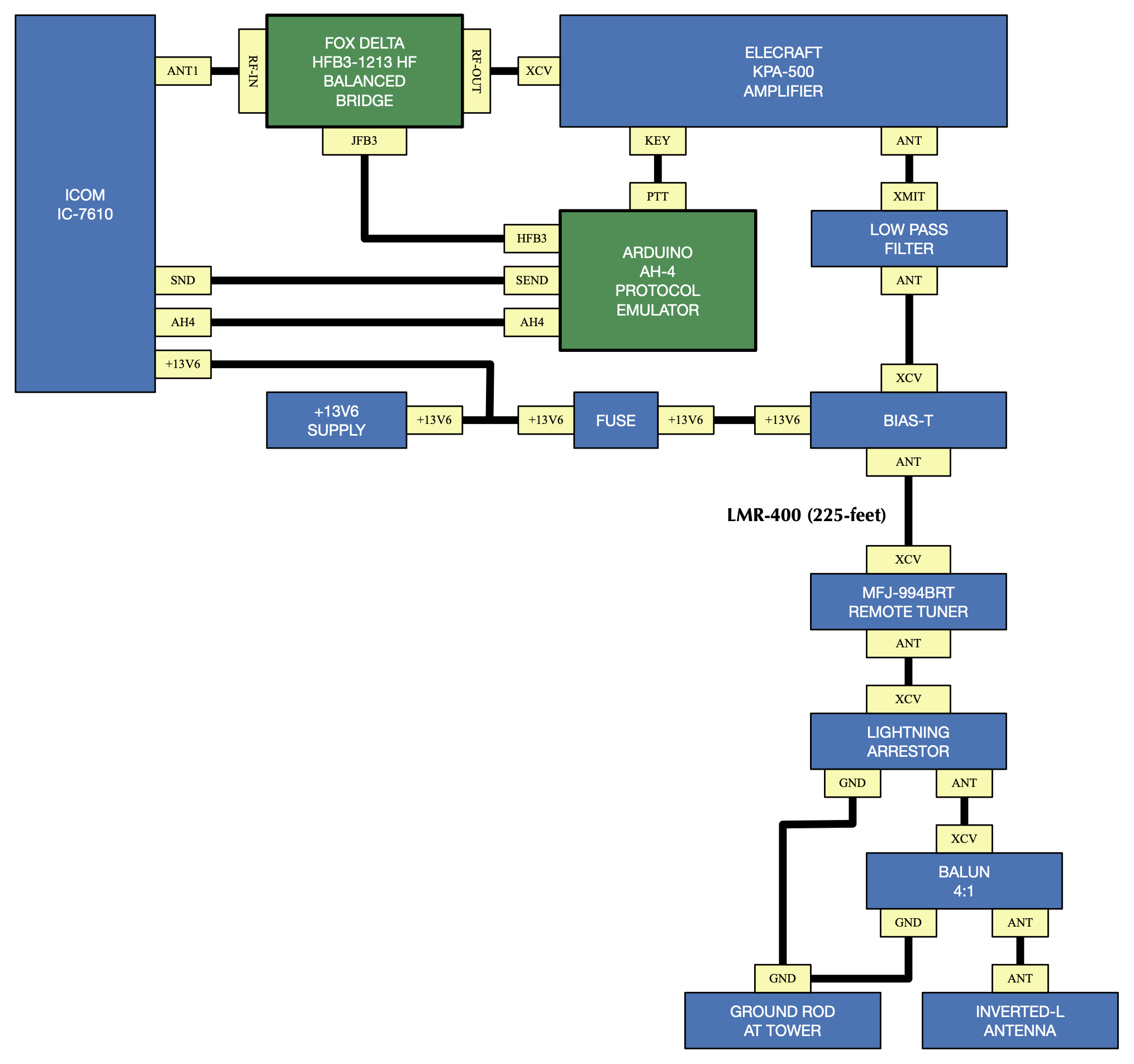
The following block diagram shows haw the station is configured where only AH4 Emulation is required (ie. no repeat operation). Note that the Fox Delta HFB3 HF Balanced Bridge is placed between the transmitter and the amplifier, where the power level will not exceed 100-watts. This placement of the Fox Delta HFB3 is between the transceiver and the amplifier. The amplifier is bypassed (inhibited) during the tuning process by blocking the routing of the transceiver SEND singal to the amplifier PTT signal. This results in the transmission of a low power carrier, resulting from the AH4 KEY line assertion to the transceiver, during the tuning cycle and prevents damage to the auto-tuner by avoiding the auto-tune process at power levels that exceed the limits of the auto-tuner during the tuning sequence.
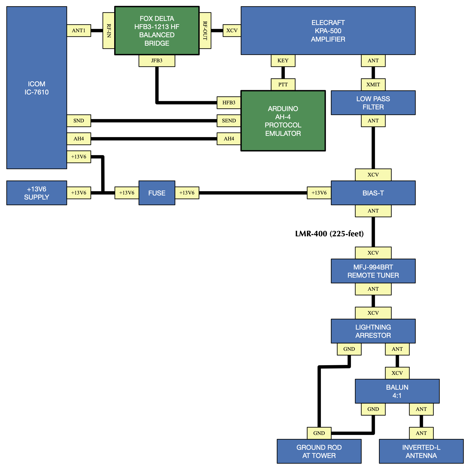
Under normal operation, a transmitter output level of 23-watts produces 500-watts output from the Elecraft KPA-500 amplifier. When tuning, in response to assertion of the AH4 KEY signal, the transmitter output level is approximately 10-watts.
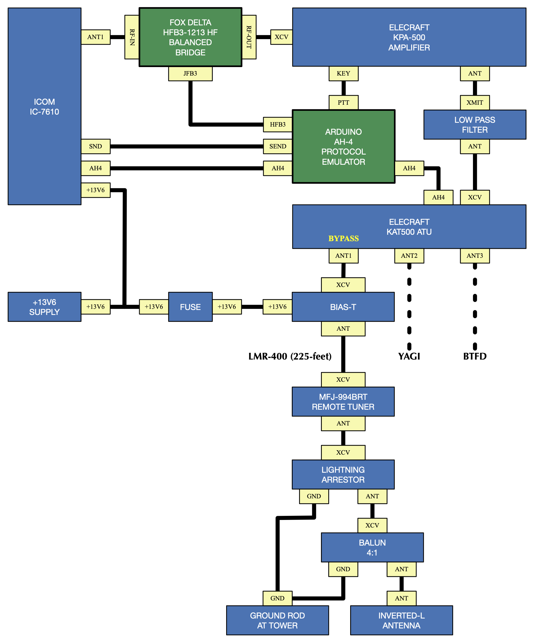
The following block diagram shows haw the station is configured where both AH4 Emulation and AH4 repeat operation are required. Note that the Fox Delta HFB3 HF In this configuration, the station configuration would have the MFJ-994BRT on one KAT500 antenna port and that antenna port must be operated in the BYPASS mode. Note that it is not possible to force a specified antenna port to always be in BYPASS mode with the KAT500 Utility, so this must be managed by the radio operator.
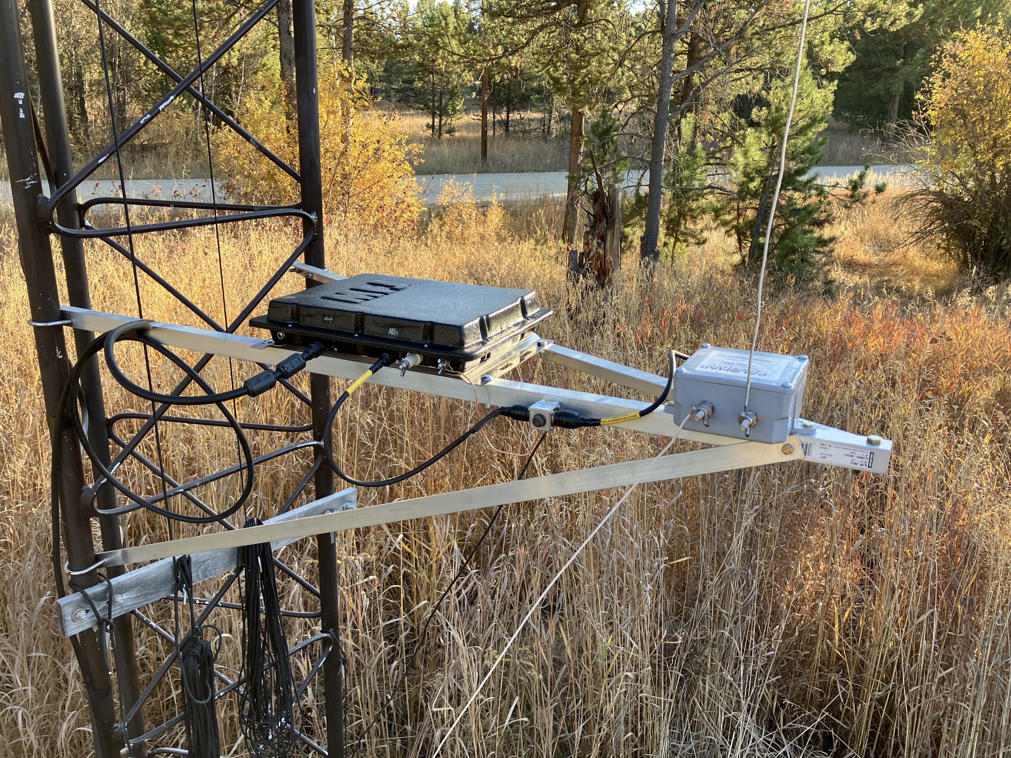
MFJ-994BRT Remote Auto-Tuner installed on tower stand-off with lightning arrestor and 4:1 balun. The total lenght of the stand-off arm is 4-feet, and is mounted approximately 6-feet above the ground to keep the installation above the normal snow depth. A ground rod is installed at the base of the tower.
An identical stand-off is mounted at the 56-foot level of the 60-foot tower.
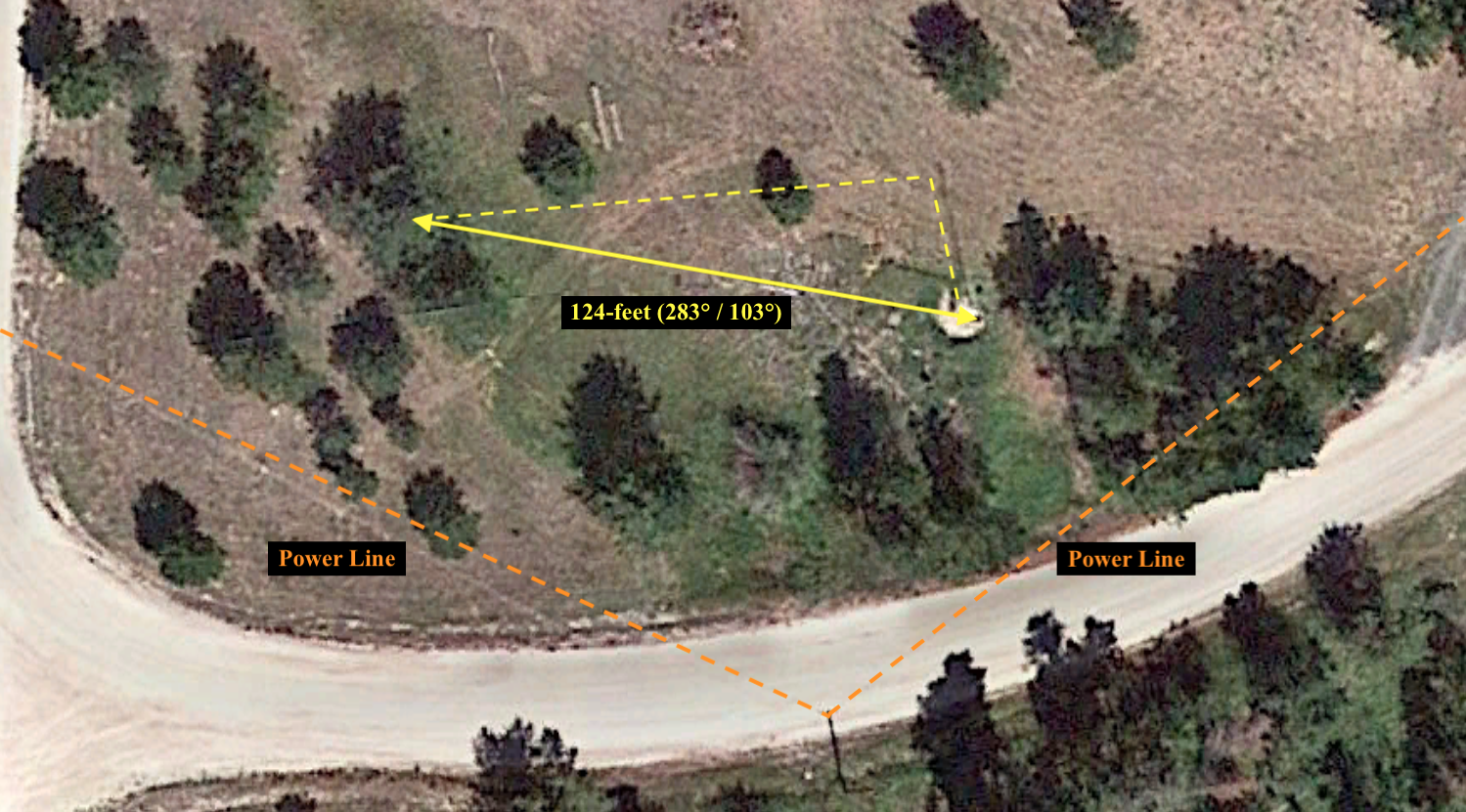
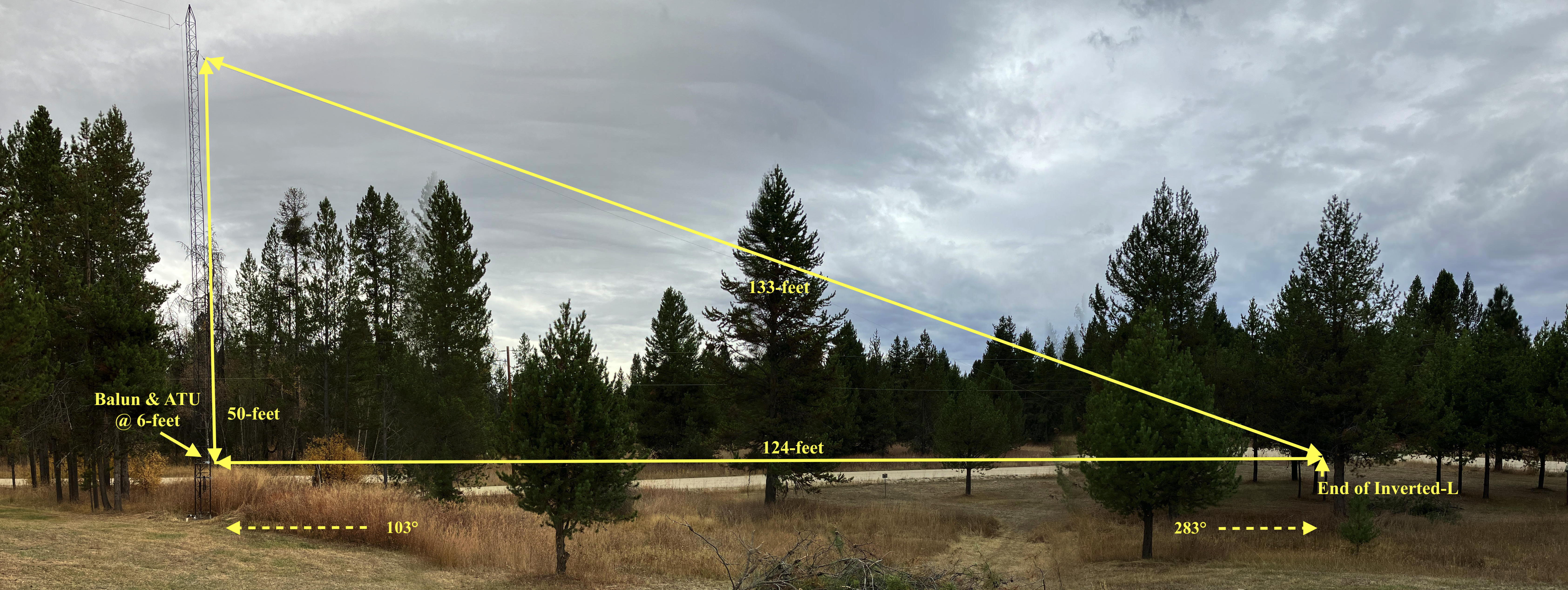
Arial view of Inverted-L antenna layout. The end of the Inverted-L that is opposite to the feed point is tied off to a tree that is 124-feet from the tower. There are no trees inside of the "L". The vertical segment of wire is 50-feet and the sloping portion is 130-feet long, for a total wire length of 180-feet.
Tower, tower-stand-offs and Inverted-L antenna.
The board supports two operating modes. In the first operating mode, MODE A / EMULATION, the AH4 ATU Emulator will provide handshanking with the AH4 protocol interface with the transceiver, using the Fox Delta HFB3-1213 HF Balance Bridge for VSWR measurement in support of the MFJ-994BRT Remote Tuner. In the second operating mode, MODE B / REPEAT, the AH4 ATU Emulator will repeat the AHR protocol signals between the transceiver and a secondary tuner that is attached to the AH4 ATU Emulator to enable the secondary tuner to provide antenna selection and antenna matching for antennas that are directly attached to the secondary tuner and are not connected through the MFJ-994BRT Remote Tuner.
MODE A - EMULATION - Auto-Tuning Initiated Manually
Select the antenna port on the KAT500 auto-tuner that has the MFJ-994BRT connected to it, and place the KAT500 auto-tuner into BYPASS mode.
The Icom IC-7610 MENU ▸ SET ▸ FUNCTION ▸ TUNER ▸ PTT START should be set to OFF.
In manually invoked tuning, the TUNE button on the AH4 Protocol Emulator is pressed to cause the AH4 Protocol Emulator to issue a request to the Icom transceiver to initiate an auto-tuning sequence. This request is made by asserting the AH4 KEY signal to the transceiver. Keying of an amplifier will be inhibited during the auto-tuning sequence. Once the auto-tune sequence has completed, keying of the amplifier will be enabled if a valid and stable VSWR resulted from the auto-tuning sequence. If a value and stable VSWR was not achieved, the amplifier will remain bypassed and subsequent transmissions will not key the amplifier.
MODE A - EMULATION - Auto-Tuning Initiated from Transceiver
Select the antenna port on the KAT500 auto-tuner that has the MFJ-994BRT connected to it, and place the KAT500 auto-tuner into BYPASS mode.
The Icom IC-7610 MENU ▸ SET ▸ FUNCTION ▸ TUNER ▸ PTT START should be set to ON.
Tuning from the transceiver is best achieved by setting up the transceiver to automatically iniitate an auto-tuning sequence on the first key-down event after the transceiver frequency has been changed.
MODE B - REPEAT - Auto-Tuning Initiated Manually
Select the antenna port on the KAT500 auto-tuner that has an antenna other than the MFJ-994BRT connected to it, and place the KAT500 auto-tuner into MANUAL or AUTO mode.
The Icom IC-7610 MENU ▸ SET ▸ FUNCTION ▸ TUNER ▸ PTT START should be set to OFF.
In mode B, the AH4 Protocol Emulator will pass the amplifier key line through so that it is controlled by another auto-tuner, such as the an Elecracft KAT500 auto-tuner. The AH4 Protocol Emulator will simply repeat the START signal from the transceiver to the KAT500, and repeat the KEY signal from the KAT500 to the transceiver. Manual tuning is initiated by pressing the TUNE button on the KAT500.
MODE B - REPEAT - Auto-Tuning Initiated from Transceiver
Select the antenna port on the KAT500 auto-tuner that has an antenna other than the MFJ-994BRT connected to it, and place the KAT500 auto-tuner into MANUAL or AUTO mode.
The Icom IC-7610 MENU ▸ SET ▸ FUNCTION ▸ TUNER ▸ PTT START should be set to ON.
Operation is identical to MODE A Auto-Tuning Initiated from Transceiver, but because the AH4 Protocol Emulator is simply repeating the AH4 protocol signals between the transceiver and the KAT500 auto-tuner, the KAT500 will perform the handshaking with the transceiver instead of the AH4 Protocol Emulator.
NOTE: Switching from MODE A / EMULATION to MODE B / REPEAT will remove any amplifier lock-out. Switching back from MODE B / REPEAT to MODE A / EMULATION will not restore the amplifier lock-out until an auto-tune sequence is started.
This section provides an evaluation of the performance of the AH4 Protocol Emulator. An evaluation of the MFJ-994BRT Remote Auto-Tuner is not provided. In all cases, a tuning solution has previously been resolved and the tuning parameters have been stored in memory within the MFJ-994BRT Remote Auto-Tuner. This means that all applications of a tuning solution with the AH4 Protocol Emulator will draw tuning coefficients from memory, resulting in a very rapid tuning solution.
MODE A / EMULATION - Auto-Tuning Initiated from Transceiver
The transceiver has been set to initiate an auto-tuning sequence upon first transmission after moving frequency (ie. the Tuner section of the Function page has the "PTT Start" parameter set to "ON").
Operation of the AH4 Emulator in EMULATION mode appears to be functioning correctly.
MODE A / EMULATION - Auto-Tuning Initiated from AH4 Protocol Emulator
The ability of the transceiver to initiate an auto-tuning sequence upon first transmission after moving frequency has been disabled for this test (ie. the Tuner section of the Function page has the "PTT Start" parameter set to "OFF"). Auto-tuning sequences were initiated manually, after a frequency change, by pressing the TUNE button on the AH4 Protocol Emulator.
MODE A / EMULATION - Auto-Tuning Initiated from ION2G as a prefix operation to an ALE Call
The ability of the transceiver to initiate an auto-tuning sequence upon first transmission after moving frequency has been disabled for this test (ie. the Tuner section of the Function page has the "PTT Start" parameter set to "OFF"). Auto-tuning sequences were initiated by a short tuning tone that is transmitted by the ION2G software as a prefix operation to an ALE Call.
It should be noted that the ION2G software sends the prefix tuning tone at the same amplitude as an ALE Call. This means that the KPA-500 amplifier will have a short transmission at full-power, with the incorrect tuning parameters applied at the MFJ-994BRT Remote Auto-Tuner. This is followed by a short pause with no transmission, where the MFJ-994BRT will then apply the tuning parameters from memory, and then a resumption of transmission at full-power to initiate the ALE Call.
The ION2G prefix tuning tone duration was set to 700 milliseconds, with a non-keyed gap following the tuning tone with a 100 millisecond duration.
MODE B / REPEAT - Invoking Manual Tune on the Elecraft KAT500
The goals of simplifying the auto-tuning and amplifier sequencing have been achieved when operating with the antenna selection routing RF to the MFJ-994BRT / Inverted-L antenna. For this configuration, operation is as simple as setting up the radio to auto-tune on key-down. After moving frequency, key the transceiver and wait for the auto-tune cycle to complete. After the auto-tune cycle has completed, normal operation is available.
The goals of simplifying the auto-tuning and amplifier sequencing where reliance on the KAT-500 auto-tuner antenna selection to route RF to other antenna ports on the KAT-500 have not been achieved. The inability of the KAT-500 to remember and apply the BYPASS mode, based on antenna selection, is the largest hurdle to be overcome. The only viable configuration where reliance on the KAT-500 auto-tuner antenna selection is necessary is where the other antenna ports (ie. ports other than the port supporting the MFJ-994BRT / Inverted-L) are able to operate in bypass mode with no KAT-500 tuning being required.
Although this project achieves all of the goals where operation is confined to the MFJ-994BRT / Inverted-L antenna, this project is not successful in achieving full frequency agility, at a high power level, across a multiple antenna configuration.
The configuration where this project succeeds is as follows:
The above configuration may simply omit the Emulate / Repeat switch.
This project is considered to be incomplete. A future modification will attempt to address the current issues by interfacing a serial port between the AH4 Emulator and the KAT500 to apply command control to (1) place the KAT500 in bypass when entering emulation mode, and (2) place the KAT500 in manual tuning mode when entering repeat mode. A breif low power transmission will be needed immediately after the transission of the mode switch and the sending of the command to allow the KAT500 to apply the frequency dependent antenna selection, followed by a full tuning cycle. Stay tuned...
73, Ray Montagne (W7CIA)